Publication 1747-RM001G-EN-P - November 2008
Processor Files 1-3
Status File (File S2:)
You cannot add to or delete from the status file. See Table 1.2 to understand
how to address various bits and words within the status file. You can address
various bits and words as follows.
Bit Data File (B3:)
File 3 is the bit file, used primarily for bit (relay logic) instructions, shift
registers, and sequencers. The maximum size of the file is 256 1-word
elements, a total of 4096 bits. You can address bits by specifying the element
number (0 to 255) and the bit number (0 to 15) within the element. You can
also address bits by numbering them in sequence, 0 to 4095.
You can also address elements of this file. See Table 1.3 for a detailed format
description. Note the two different possible formats that can be used.
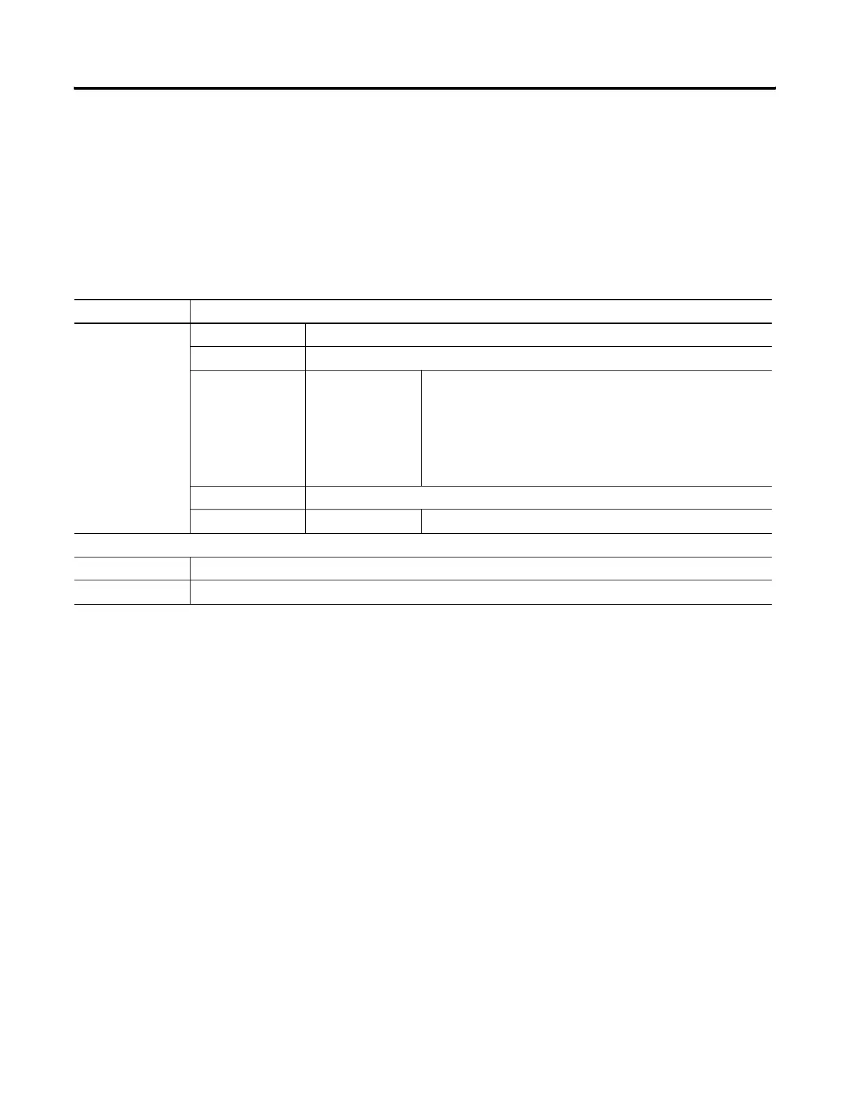
Table 1.2 Status File Addressing Format
Format Explanation
S:e/b S Status file
: Element delimiter
e Element number Ranges from 0 to 15 in a fixed or SLC 5/01 controller,
0 to 32 in an SLC 5/02,
0 to 82 in an SLC 5/03 and
0 to 82 in an SLC 5/05,
0 to 96 in an SLC 5/04 OS400, and
0 to 163 in an SLC 5/04 OS401 processors.
These are 1-word elements. 16 bits per element.
/ Bit delimiter
b Bit number Bit location within the element. Ranges from 0 to 15.
Examples:
S:1/15 Element 1, bit 15. This is the “first pass” bit, which you can use to initialize instructions in your program.
S:3 Element 3. The lower byte of this element is the current scan time. The upper byte is the watchdog scan time.

 Loading...


