Publication 1747-RM001G-EN-P - November 2008
SLC Communication Instructions 12-27
MSG Instruction Setup Screen Status Bits
The column in the table below lists the various status bits associated with the
SLC 500 MSG instruction as displayed in the RSLogix 500 MSG instruction
setup screen.
• Timeout Bit TO (word 0, bit 8):Set this bit in your application to
remove an active message instruction from processor control. You must
use your own timeout control routine for the SLC 5/02 MSG
instruction (See Figure 12.1 on page 12-6). You may use the internal
timeout control for SLC 5/03 and higher processors. For these
processors, we recommend using the built-in timeout control because it
simplifies the user program. Default values are 5 seconds for SLC 5/03,
SLC 5/04, and SLC 5/05 channel 0, and 23 seconds for SLC 5/05
channel 1.
To utilize the internal timeout control, a value greater than 0 must be
entered for the MSG instruction timeout parameter. A timeout value of
0 means no timeout value. In other words, if communication is
interrupted, the processor will wait forever for a reply. If an
acknowledgement is received (as indicated by the ST bit being set), but
the reply is not received, the MSG instruction will appear to be locked
up, although it is merely waiting for the reply.
When a value greater than 0 is entered for the MSG timeout parameter
and communication is interrupted, the MSG instruction will timeout
and error after the time expires, allowing the user program to retry the
same message if desired.
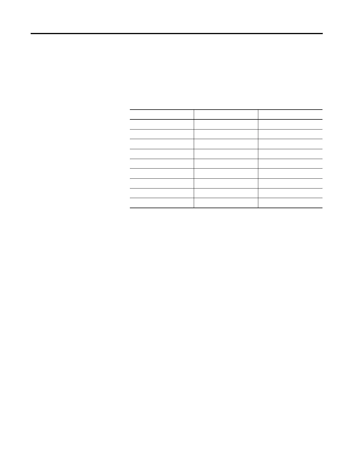
Table 12.9 MSG Instruction Setup Screen Status Bits
Bit Definition Bit Mnemonic Bit Address
Ignore if timed out TO 08
To be retried NR 09
Awaiting execution EW 10
Continuous run CO 11
Error ER 12
Message done DN 13
Message transmitting ST 14
Message enabled EN 15
Waiting for queue space WQ 07

 Loading...


