
 Loading...
Do you have a question about the Allen-Bradley SLC 500 Series and is the answer not in the manual?
| Programming Software | RSLogix 500 |
|---|---|
| Series | SLC 500 |
| Category | Controller |
| Manufacturer | Allen-Bradley (Rockwell Automation) |
| I/O Capacity | Up to 4096 I/O points |
| Communication Ports | DH-485 |
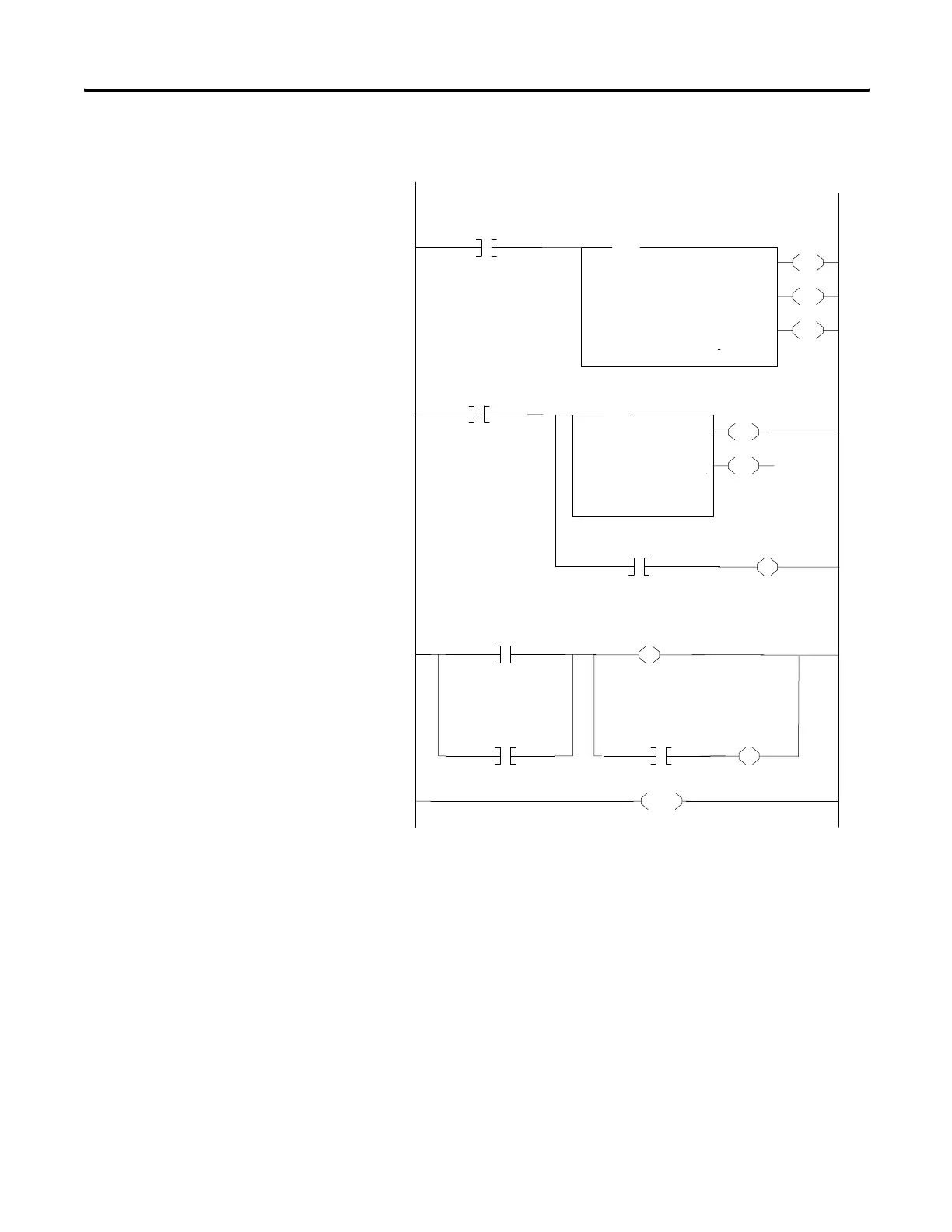
| Programming Languages | Ladder Logic |
| Operating Temperature | 0 to 60 °C (32 to 140 °F) |
| Relative Humidity | 5% to 95% (non-condensing) |
| Memory | 4K to 64K words (depending on the processor) |
| Power Supply | AC or DC (depending on the module) |


