Publication 1747-RM001G-EN-P - November 2008
Basic Instructions 2-7
The SLC 500 and SLC 5/01 processors allow you to use only one OSR
instruction per rung.
The SLC 5/02 and higher processors allow you to use one OSR instruction
per output in a rung. They also allow input conditions after the OSR
instruction. Input branching around an OSR instruction is not allowed.
Timer Instructions
Overview
Entering Parameters
These are several parameters associated with Timer instructions. The
following paragraphs detail the operation of the timer instruction.
Accumulator Value (.ACC)
This is the time elapsed since the timer was last reset. When enabled, the timer
updates this continually.
Preset Value (.PRE)
This specifies the value which the timer must reach before the controller sets
the done bit. When the accumulated value becomes equal to or greater than
the preset value, the done (DN) bit is set. You can use this bit to control an
output device.
Preset and accumulated values for timers range from 0 to +32,767. If a timer
preset or accumulated value is a negative number, a runtime error occurs.
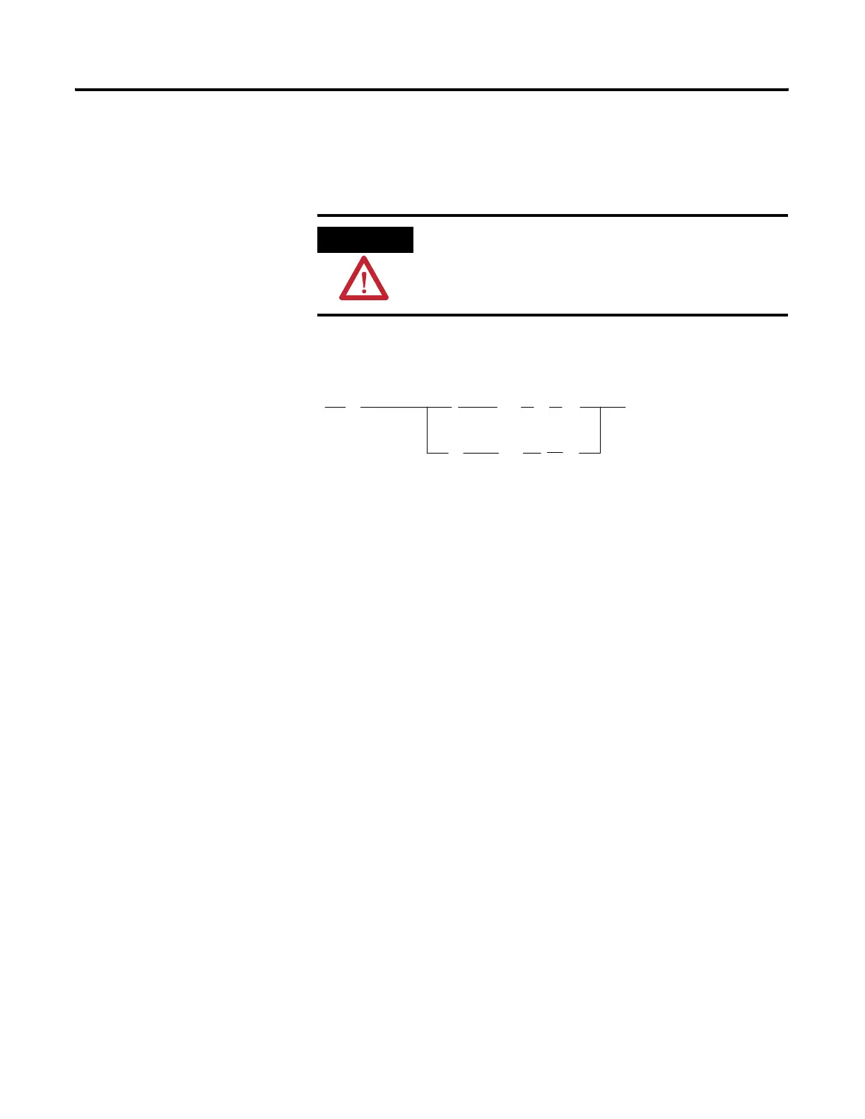
ATTENTION
When using a SLC 500 or SLC 5/01 processor, do not
place input conditions after the OSR instruction in a
rung. Unexpected operation may occur.
( )
O:3.0
0
]/[
B3
1
]/[
B3
5
[OSR]
B3
3
( )
O:3.0
1
] [
B3
2
] [
B3
4
] [
I:1.0
0
[OSR]
B3
0
SLC 5/02 (and higher) Processors

 Loading...


