Publication 1747-RM001G-EN-P - November 2008
Messaging Examples 15-3
The default Passthru Link ID for the SLC 5/03, 5/04 and 5/05 processors
channel 0 port is 1.
The default Passthru Link ID for the SLC 5/03, 5/04 and 5/05 processors
channel 1 port is 2.
Refer to Chapter 14 for more information regarding passthru.
SLC 5/03 Passthru
Examples
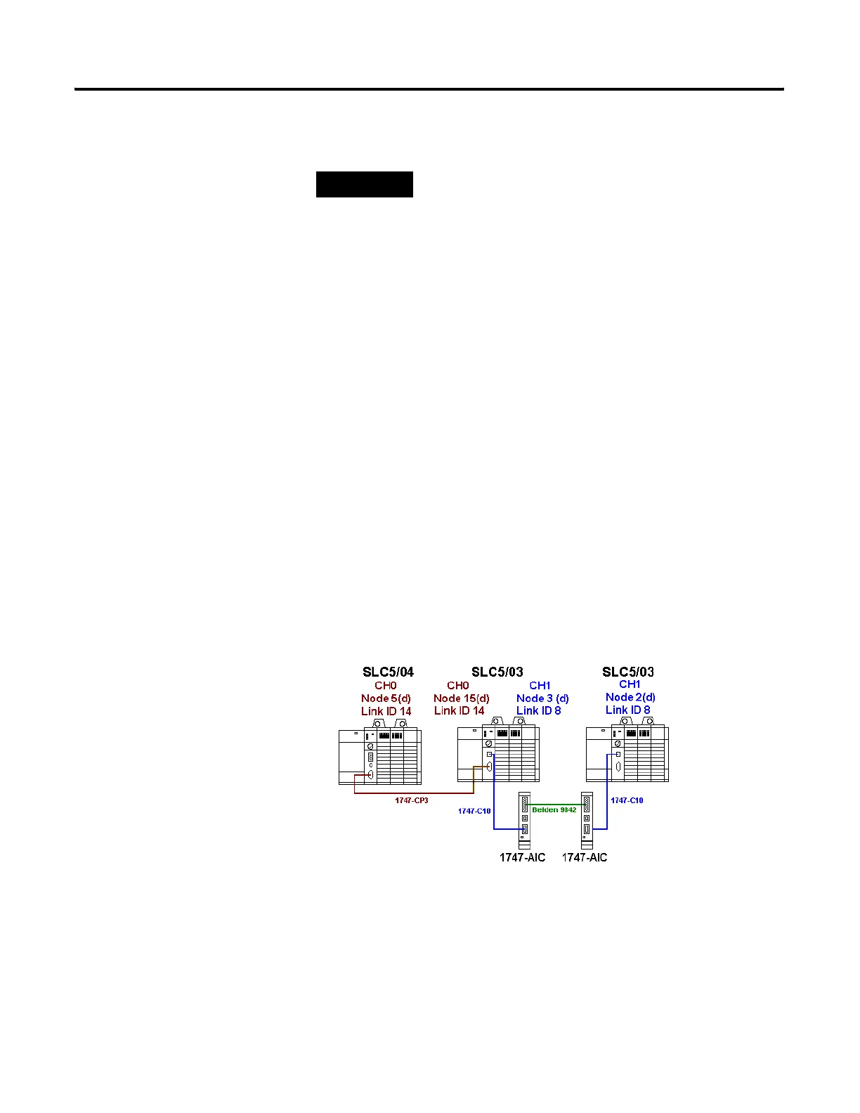
Passthru Example: DF1 to DH-485
The following illustrates a SLC 5/03 processor as a passthru processor. The
SLC 5/03 processor will forward messages received on the DF1 network
(channel 0) to the DH-485 network (channel 1). For this example, the SLC
5/03’s configuration bits are set to the following values.
• DF1 Pass-Thru Enable bit (S2:34/5) is set
• DH-485 Pass-Thru Disable bit (S2:34/0) is set
• DF1 Remote/Local Pass-Thru (S2:34/6) is clear
The DF1 Pass-Thru Enable Bit (S2:34/5) enables messages to be passed to
and from the channel 0 DF1 network from and to the channel 1 DH-485
network. This bit must be set to enable DH-485-to-DF1 passthru.
TIP
Link ID’s are modified in each processors Channel
Configuration properties.

 Loading...


