Publication 1747-RM001G-EN-P - November 2008
Basic Instructions 2-15
Using Status Bits
The accumulated value is retained after the CTD instruction goes false, or
when power is removed from and then restored to the controller. Also, the on
or off status of counter done, overflow, and underflow bits is retentive. The
accumulated value and control bits are reset when the appropriate RES
instruction is executed. The CD bits are always set prior to entering the REM
Run or REM Test modes.
High-speed Counter (HSC)
The High-speed Counter is a variation of the CTU counter. The HSC
instruction is enabled when the rung logic is true and disabled when the rung
logic is false.
The HSC instruction counts transitions that occur at input terminal I:0/0. The
HSC instruction does not count rung transitions. You enable or disable the
HSC rung to enable or disable the counting of transitions occurring at input
terminal I:0/0. We recommend placing the HSC instruction in an
unconditional rung.
The HSC is a special CTU counter for use with 24 VDC SLC fixed controllers.
The HSC’s status bits and accumulated values are non-retentive.
Table 2.11 Setting CTD Status Bits
This Bit Is Set When And Remains Set Until
One of the Following
Count Down Underflow Bit
UN (Bit 11)
accumulated value wraps
around to +32,767 (from
-32,768) and continues
counting down from there
a RES instruction having the
same address as the CTD
instruction is enabled. OR
the count is incremented
greater than or equal to
+32,767 with a CTU
instruction
Done Bit DN (Bit 13) accumulated value is equal
to or greater than the preset
value
the accumulated value
becomes less than the
preset
Count Down Enable Bit CD
(Bit 14)
rung conditions are true rung conditions go false OR
a RES instruction having the
same address as the CTD
instruction is enabled
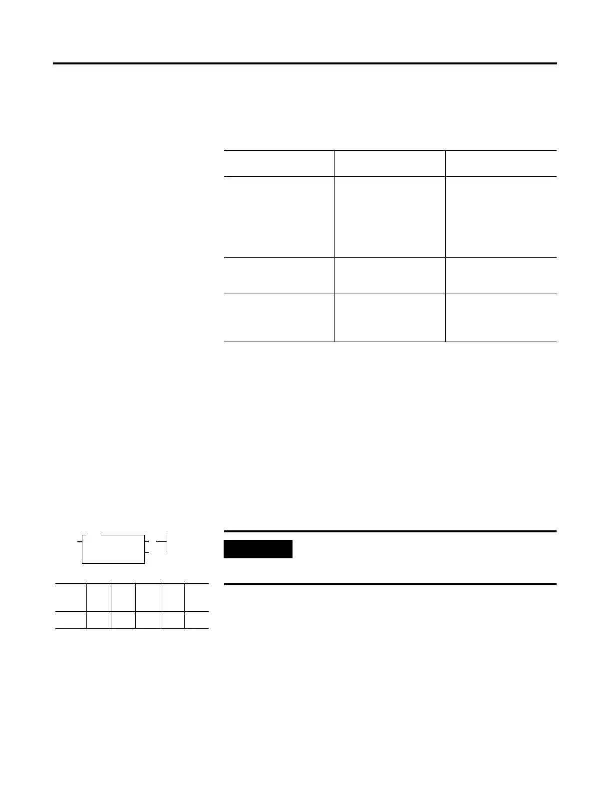
HIGH SPEED COUNTER
Counter C5:0
Preset 120
Accum 0
(CU)
(DN)
HSC
Output Instruction
Fixed SLC
5/01
SLC
5/02
SLC
5/03
SLC
5/04
SLC
5/05
•
IMPORTANT
Do not place the XIC instruction with address I:0/0
in series with the HSC instruction because counts
will be lost.

 Loading...


