Publication 1747-RM001G-EN-P - November 2008
SLC Communication Instructions 12-5
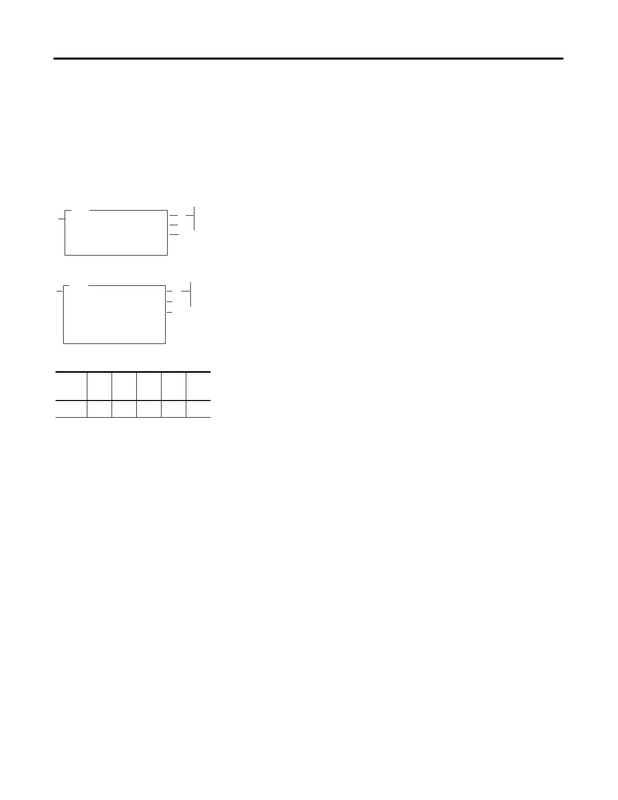
Message Instruction
Overview
The message instruction is an output instruction that lets you read or write
data from one processor to another processor via the communication
channel(s). The SLC 5/02 processor can service one message instruction at
any given time. The SLC 5/03 and higher processors can service up to four
message instructions per channel at a time, for a maximum of eight message
instructions at any given time. Only one message instruction is serviced at a
time for Modbus RTU Master protocol.
To invoke the MSG instruction, toggle the MSG instruction rung from
false-to-true. Do not toggle the rung again until the MSG instruction has
successfully or unsuccessfully completed the previous message, indicated by
the processor setting either the DN or ER bit.
MSG Instruction Operation
SLC 5/02 - Although only one message instruction can be serviced at a time,
the processor may hold several messages enabled and waiting (control block
status bits EN and EW set). Waiting messages are serviced one at a time in
sequential order.
Ladder logic should be included with every SLC 5/02 MSG instruction to time
out the message in the event that the MSG starts transmitting successfully
(MSG control block ST bit set), but the response is not received back in a
reasonable amount of time. See Figure 12.1 and Figure 12.2 on how to use the
MSG control block TO bit to accomplish this.
(EN)
(DN)
(ER)
READ/WRITE MESSAGE
Read/write
Target Device
Control Block
Control Block Length
Setup Screen
7
MSG
READ/WRITE MESSAGE
Type
Read/write
Target Device
Local/Remote
Control Block
Control Block Length
Setup Screen
14
(EN)
(DN)
(ER)
MSG
SLC 5/02
SLC 5/03 and higher
Output Instruction
Fixed SLC
5/01
SLC
5/02
SLC
5/03
SLC
5/04
SLC
5/05
••••

 Loading...


