Publication 1747-RM001G-EN-P - November 2008
9-26 Proportional Integral Derivative Instruction
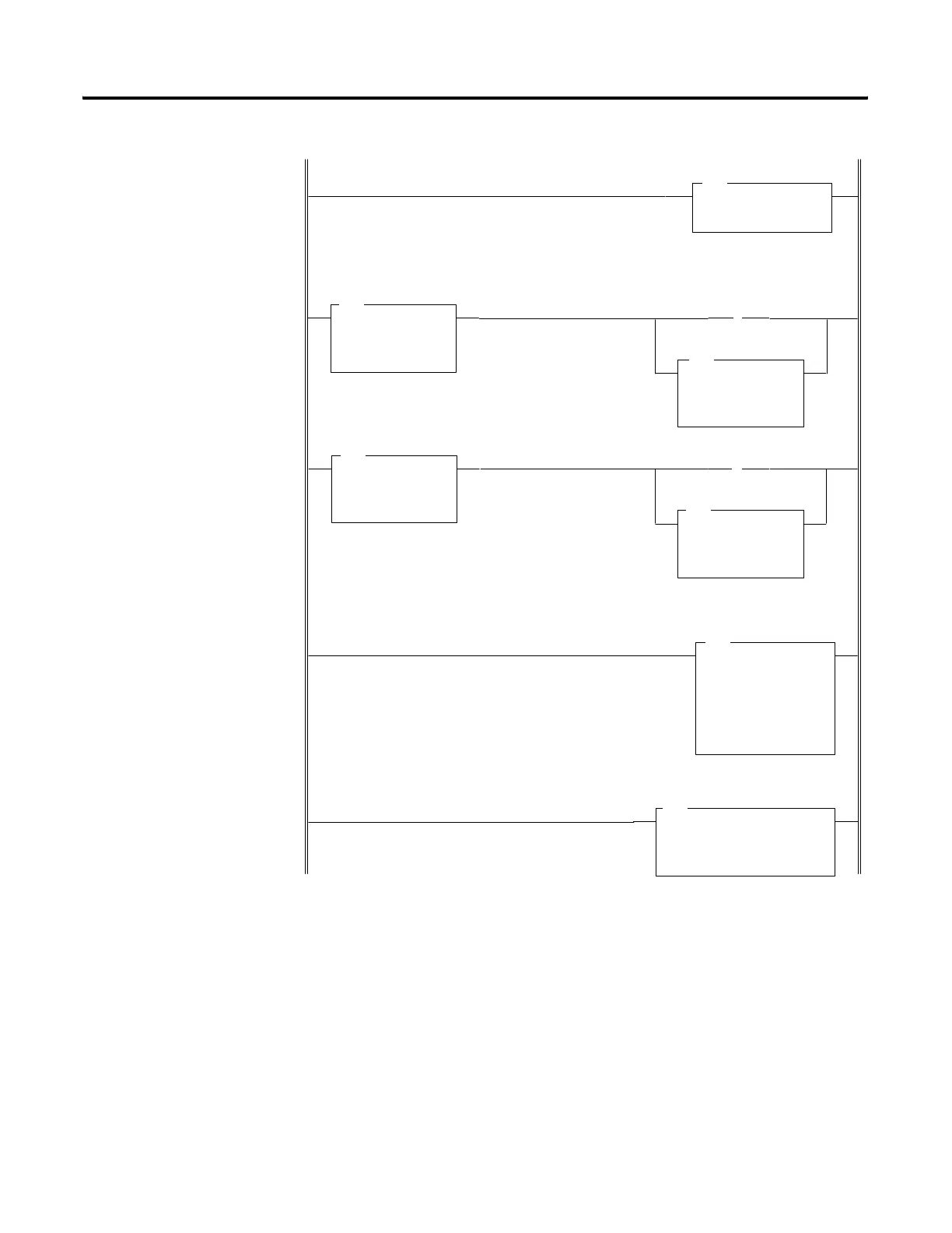
The STI routine should have a time interval equal to the setting of the PID
“loop update” parameter.
SCALE
Source I:1.0
0
Rate [/10000] 12499
Offset –4096
Dest N10:28
0
LESS THAN
Source A I:1.0
0
Source B 3277
GREATER THAN
Source A I:1.0
0
Source B 16384
MOVE
Source 3277
Dest I:1.0
0
IMMEDIATE IN w MASK
Slot I:1.0
Mask FFFF
B3
0
MOVE
Source 16384
Dest I:1.0
0
B3
1
PID
Control Block N10:0
Process Variable N10:28
Control Variable N10:29
Control Block Length 23
LES
GRT
SCL
MOV
MOV
IIM
PID
(L)
(L)
This rung immediately updates the analog input used for PV.
These two rungs ensure the analog input value to be scaled remains within the limits of 3277 to 16384.
This is necessary to prevent “out of range” conversion errors in both the SCL and PID instructions. The latch
bits can be used elsewhere in your program to identify the particular out of range condition that occurred.
Under range
Over range
The source to be scaled is the input I:1 and its destination is the process variable of the PID instruction.
These values are calculated knowing that the input range is 3277 to 16384, while the scaled range (PV) is 0
to 16383.
Rung
3:0
Rung
3:1
Rung
3:2
Rung
3:3
Rung
3:4

 Loading...


