Publication 1747-RM001G-EN-P - November 2008
ASCII Instructions 10-23
• Characters Sent (POS) is the number of characters that the processor
sent to the display area (0 to 82). Only after the entire string is sent is
this field updated (no running total for each character is stored). This
field is display only. This value can be greater than the string length if
inserted values from in-line indirection are used. If the string length is
greater than 82, the string written to the destination is truncated to 82
characters.
• Error displays the hexadecimal error code that indicates why the ER bit
was set in the control data file (R6). See page 10-24 for error code
descriptions.
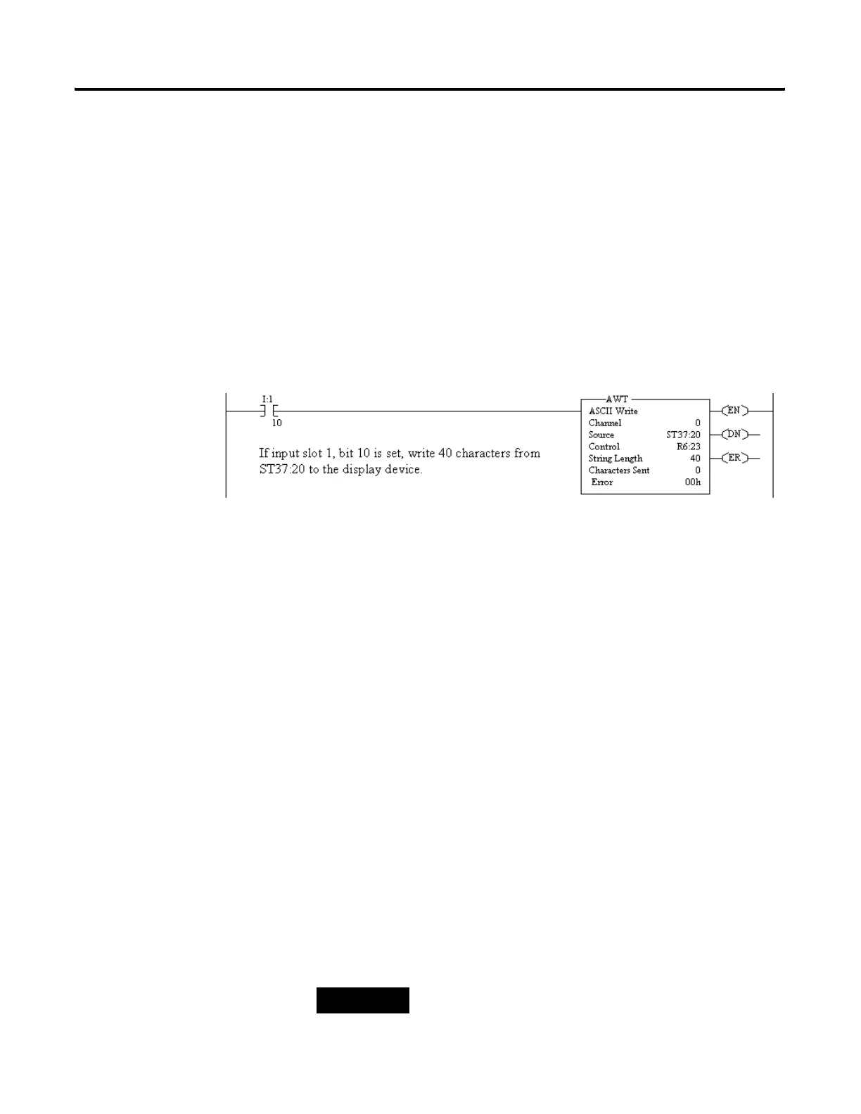
Example
When the rung goes from false-to-true, the control element Enable (EN) bit is
set. When the instruction is placed in the ASCII queue, the Queue bit (EU) is
set. The Running bit (IN) is set when the instruction is executing. The DN bit
is set on completion of the instruction.
Forty characters from string ST37:40 are sent through channel 0. The Done
bit (DN) is set and a value of 40 is present in the POS word of the ASCII
control block.
When the program scans the instruction and finds the Done bit (DN) set, the
processor then sets the Synchronous Done bit (EM) to act as a secondary
done bit corresponding to the program scan.
The Error bit (ER) is set during execution of the instruction if:
• the modem is disconnected (control line selection is other than “NO
HANDSHAKING”).
• port is in System Mode and is configured for DH-485 or DF1 Radio
Modem.
• the Unload bit (UL) is set. The instruction stops executing, but received
characters are sent to the destination.
• an ACL to clear the transmit buffer is executed, removing the AWT
instruction from the ASCII queue.
TIP
For information on the timing of this instruction, refer
to the timing diagram on page 10-16.

 Loading...


