Publication 1747-RM001G-EN-P - November 2008
Understanding Interrupt Routines 11-15
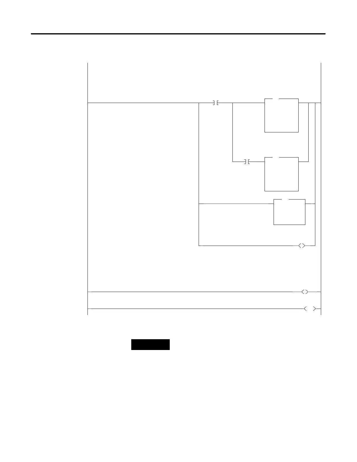
0000
B3:0
0
Indicate Valid
Measurement
SUB
Subtract
Source A
S:43
0<
Source B
N10:1
0<
Dest
N10:2
0<
SUB
S:0
3
Processor
Arithmetic
Sign
Flag
ADD
Add
Source A
32767
32767<
Source B
N10:2
0<
Dest
N10:2
0<
MOV
Move
Source
S:43
0<
Dest
N10:1
0<
MOV
U
S:5
0
Overflow
Trap
0001
L
B3:0
0
Indicate Valid
Measurement
0002
END
The following rung will measure the time difference between consecutive interrupt subroutine executions.
Integer N10.2 contains the number of microsecond "ticks" that have occured.
The following rung will set B3:0/0 to indicate that the value in N10.2 is valid.
TIP
The math overflow selection bit (S:2/14) must be set prior
to entering RUN mode.

 Loading...


