166 Rockwell Automation Publication MOTION-RM002H-EN-P-February 2018
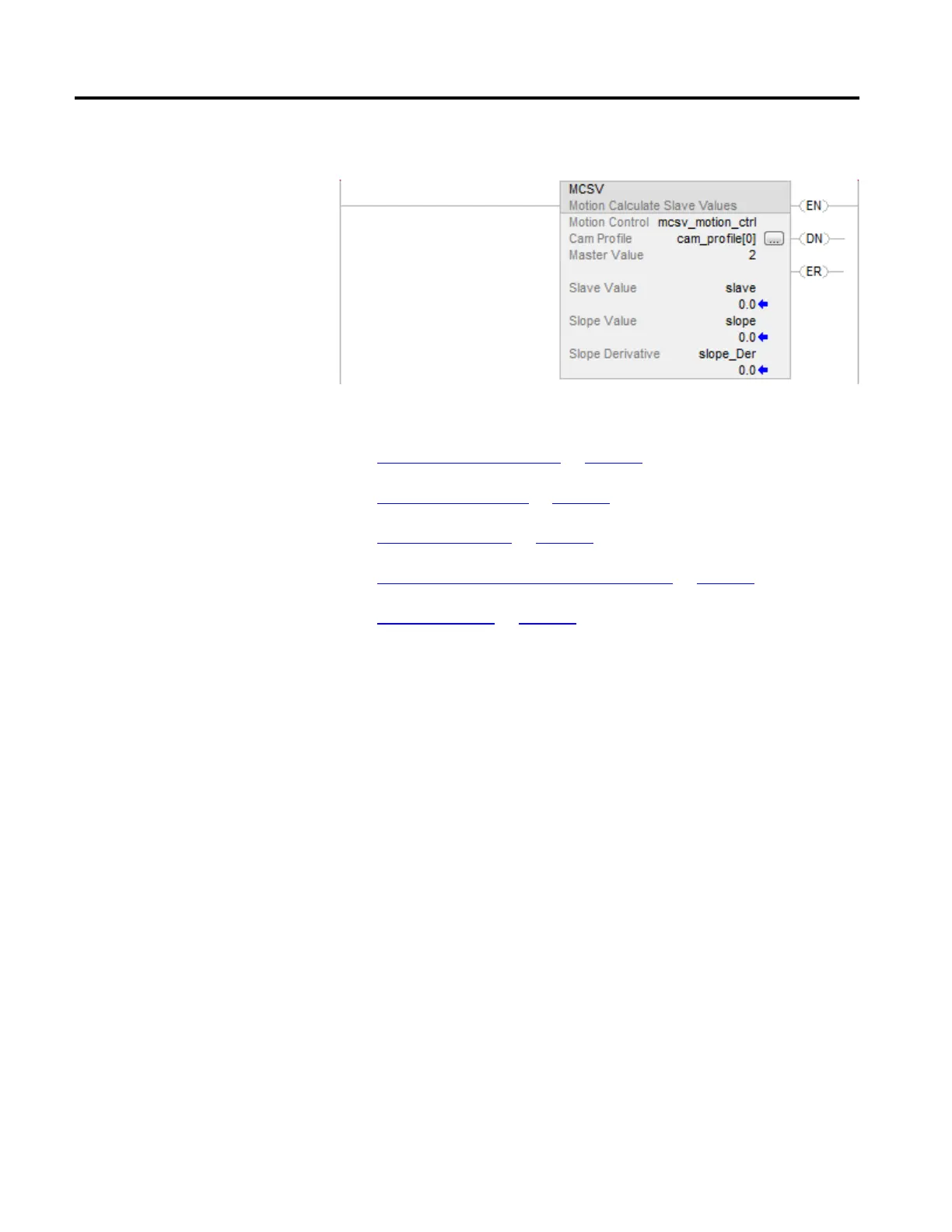
Example
See also
Motion Error Codes (.ERR) on page 557
Structured Text Syntax on page 635
Common Attributes on page 663
Multi-Axis Coordinated Motion Instructions on page 345
Data Conversions on page 669
This information applies to the CompactLogix 5370, ControlLogix 5570,
Compact GuardLogix 5370, GuardLogix 5570, Compact GuardLogix 5380,
CompactLogix 5380, CompactLogix 5480, ControlLogix 5580, and GuardLogix
5580 controllers. Controller differences are noted where applicable.
The Motion Axis Position Cam (MAPC) instruction provides electronic
camming between any two axes according to the specified Cam Profile.
When executed, the specified Slave Axis is synchronized to the designated Master
Axis using a position Cam Profile established by the Logix Designer application
Cam Profile Editor, or by a previously executed Motion Calculate Cam Profile
(MCCP) instruction. The direction of Slave Axis motion relative to the Master
Axis is defined by a flexible Direction input parameter. The camming Direction, as
applied to the slave, may be explicitly set as the Same or Opposite or set relative to
the current camming direction as Reverse or Unchanged.
To accurately synchronize the slave axis position to master axis position, an
Execution Schedule setting and an associated Master Lock Position can be
specified for the master axis. When the master axis travels past the Master Lock
Position in the direction specified by the Execution Schedule parameter, the slave
axis is locked to the master axis position according to the specified Cam Profile
beginning at the Cam Lock Position.
(MAPC)
 Loading...


