EasyManua.ls Logo

Allen-Bradley Studio 5000 Logix Emulate User Manual

Allen-Bradley Studio 5000 Logix Emulate
676 pages
To Next Page IconTo Next Page
To Previous Page IconTo Previous Page
Page #664 background imageLoading...
Page #664 background image
Chapter 12
664 Rockwell Automation Publication MOTION-RM002H-EN-P-February 2018
For example:
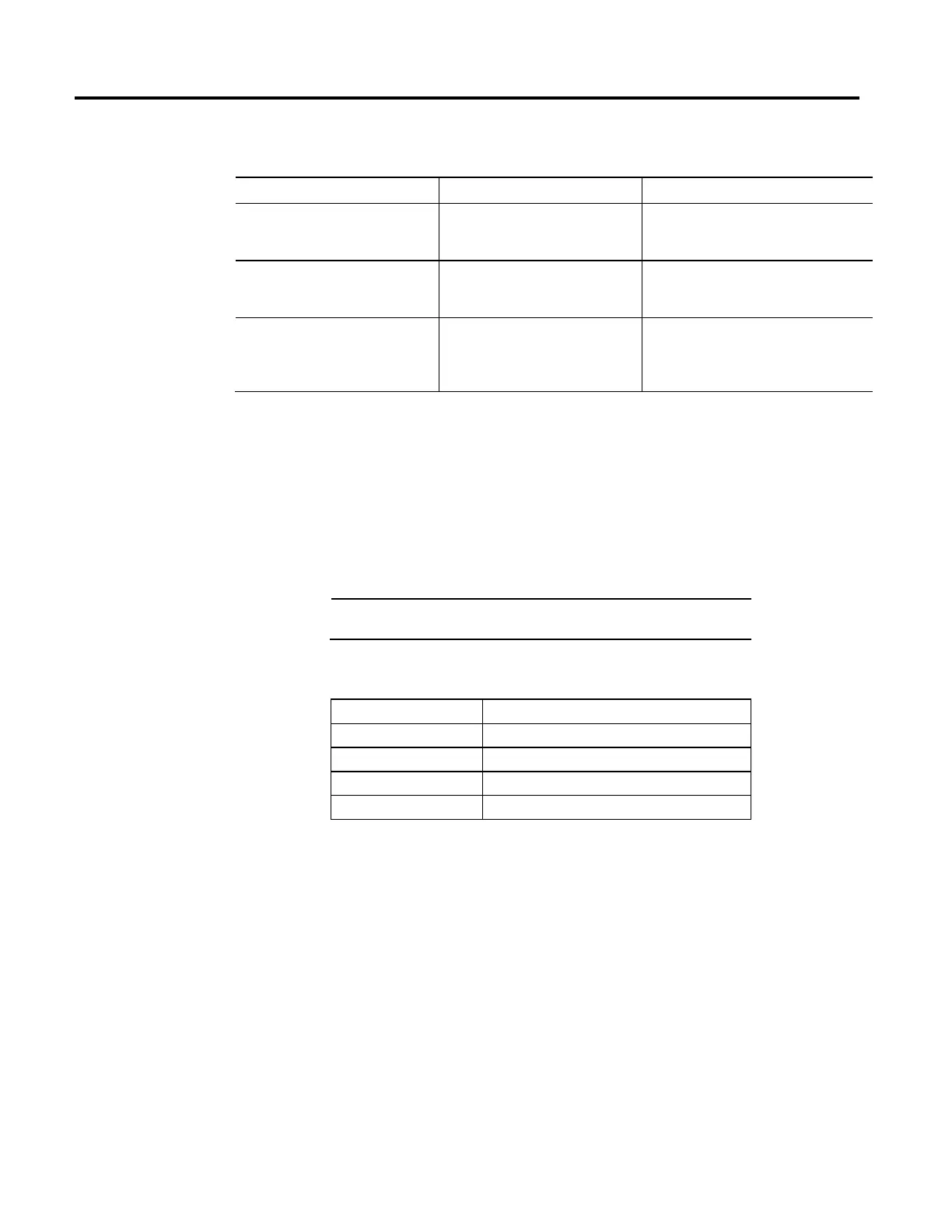
Definitions Example Description
my_list defined as DINT[10] my_list[5] This example references element 5 in the array. The
reference is static because the subscript value
remains constant.
my_list defined as DINT[10]
position defined as DINT
MOV the value 5 into position
my_list[position]
This example references element 5 in the array. The
reference is dynamic because the logic can change
the subscript by changing the value of position.
my_list defined as DINT[10]
position defined as DINT
offset defined as DINT
MOV the value 2 into position
MOV the value 5 into offset
my_list[position+offset]
This example references element 7 (2+5) in the
array. The reference is dynamic because the logic
can change the subscript by changing the value of
position or offset.
Make sure any array subscript you enter is within the boundaries of the specified
array. Instructions that view arrays as a collection of elements generate a major
fault (type 4, code 20) if a subscript exceeds its corresponding dimension.
When you enter an immediate value (constant) in decimal format (for example,
-2, 3) the controller stores the value by using 32 bits. If you enter a value in a radix
other than decimal, such as binary or hexadecimal, and do not specify all 32 bits,
the controller places a zero in the bits that you do not specify (zero-fill).
Important:
Zero-fill of immediate binary, octal or hexadecimal values less than 32
bits.
If you enter The controller stores
-1 16#ffff ffff (-1)
16#ffff (-1) 16#0000 ffff (65535)
8#1234 (668) 16#0000 029c (668)
2#1010 (10) 16#0000 000a (10)
Logix controllers handle floating point values according to the IEEE 754 standard
for floating-point arithmetic. This standard defines how floating point numbers
are stored and calculated. The IEEE 754 standard for floating point math was
designed to provide speed and the ability to handle very large numbers in a
reasonable amount of storage space.
A REAL tag stores a single-precision, normalized floating-point number
Denormalized numbers and -0.0 are treated as 0.0
If a computation results in a NAN value, the sign bit could be positive or negative.
In this situation, the software displays 1#.NAN with no sign.
Immediate values
Floating Point Values

Table of Contents

Other manuals for Allen-Bradley Studio 5000 Logix Emulate

Question and Answer IconNeed help?

Do you have a question about the Allen-Bradley Studio 5000 Logix Emulate and is the answer not in the manual?

Allen-Bradley Studio 5000 Logix Emulate Specifications

General IconGeneral
TypeEmulation Software
Supported PlatformsPC
Operating SystemWindows
Compatible ControllersControlLogix 5570, ControlLogix 5580, CompactLogix 5370, CompactLogix 5480
IntegrationIntegrated with Studio 5000 environment
Works with Studio 5000 Logix DesignerYes
Programming LanguagesLadder Logic, Function Block Diagram, Structured Text, Sequential Function Chart
Communication ProtocolsEtherNet/IP
FunctionalityController Emulation
PurposeTesting and Debugging
Use CaseProgram development, testing, training, and troubleshooting without physical PLC hardware

Summary

LOGIX 5000 Controllers Motion Instructions

Motion State Instructions

Motion Axis Fault Reset (MAFR)

Use the Motion Axis Fault Reset (MAFR) instruction to clear all motion faults for an axis. This is the only method for clearing axis motion faults.

Motion Axis Shutdown (MASD)

Use the Motion Axis Shutdown (MASD) instruction to force a specified axis into the Shutdown state.

Motion Axis Shutdown Reset (MASR)

Use the Motion Axis Shutdown (MASR) instruction to transition a group of axes from the shutdown operating state to the axis ready operating state.

Motion Move Instructions

Motion Axis Stop (MAS)

Use the Motion Axis Stop (MAS) instruction to stop a specific motion process on an axis or to stop the axis completely.

Motion Axis Home (MAH)

Use the Motion Axis Home (MAH) instruction to home an axis. Two different homing modes can be selected during axis configuration: Active or Passive.

Motion Axis Jog (MAJ)

Use the Motion Axis Jog (MAJ) instruction to move an axis at a constant speed until you tell it to stop.

Motion Axis Move (MAM)

Use the Motion Axis Move (MAM) instruction to move an axis to a specified position.

Motion Change Dynamics (MCD)

Use the Motion Change Dynamics (MCD) instruction to selectively change the speed, acceleration rate, or deceleration rate of a move profile or a jog profile in process.

Motion Calculate Cam Profile (MCCP)

The Motion Calculate Cam Profile (MCCP) instruction calculates a cam profile based on an array of cam points.

Motion Axis Position Cam (MAPC)

The Motion Axis Position Cam (MAPC) instruction provides electronic camming between any two axes according to the specified Cam Profile.

Motion Axis Time Cam (MATC)

The Motion Axis Time Cam (MATC) instruction provides electronic camming of an axis as a function of time, according to the specified Cam Profile.

Motion Group Instructions

Motion Group Stop (MGS)

The Motion Group Stop (MGS) instruction initiates a stop of all motion in progress on all axes in the specified group by a method configured individually for each axis or as a group via the Stop Mode of the MGS instruction.

Motion Group Shutdown (MGSD)

Use the Motion Group Shutdown (MGSD) instruction to force all axes in the designated group into a Shutdown state.

Motion Group Shutdown Reset (MGSR)

Use the Motion Group Shutdown Reset (MGSR) instruction to transition a group of axes from the shutdown operating state to the axis ready operating state.

Motion Event Instructions

Motion Configuration Instructions

Multi-Axis Coordinated Motion Instructions

Motion Coordinated Linear Move (MCLM)

Use the MCLM instruction to start a single or multi-dimensional linear coordinated move for the specified axes within a Cartesian coordinate system.

Motion Coordinated Circular Move (MCCM)

Use the MCCM instruction to initiate a two or three-dimensional circular coordinated move for the specified axes within a Cartesian coordinate system.

Motion Error Codes, faults, and attributes

Understand Motion Status and Configuration Parameters

Troubleshoot Axis Motion

Overview of motion-related data types

Overview of Structured Text Programming

Common attributes for Motion instructions

Related product manuals