Motion Event Instructions
Rockwell Automation Publication MOTION-RM002H-EN-P-February 2018 293
Output Cam Array Checks
The following output cam array checks are used with the MAOC instruction.
If you select Then Instruction error
an output bit less than 0 or greater than 31 the Output Cam element is not considered
Illegal Output Cam
a latch type less than 0 or greater than 3 a value of Inactive is used
an unlatch type less than 0 or greater than 5 a value of Inactive is used
a left cam position greater than or equal to the right cam
position and the latch or unlatch type is set to Position or
Position and Enable
the Output Cam element is not considered
a left cam position less than the cam start position and the latch
type is set to Position or Position and Enable
the cam start position is used
a right cam position greater than the cam end position and the
unlatch type is set to Position or Position and Enable
the cam end position is used
a duration less than or equal to 0 and the unlatch type is set to
Duration or Duration and Enable
the Output Cam element is not considered
an enable type less than 0 or greater than 3 and the latch or
unlatch type is set to Enable, Position and Enable, or Duration
and Enable
the Output Cam element is not considered
an enable bit less than 0 or greater than 31 and the latch or
unlatch type is set to Enable, Position and Enable, or Duration
and Enable
the Output Cam element is not considered
See also
Motion Arm Output Cam (MAOC) on page 262
An Output Compensation data array tag may be specified via the Logix Designer
application tag editor. The data type defines the specifics for each output bit by
specifying the characteristics of each actuator. The array indices correspond to the
output bit numbers. The number of the highest compensated output bit defines
the minimum size of this array. Changes to the output compensation take effect
immediately.
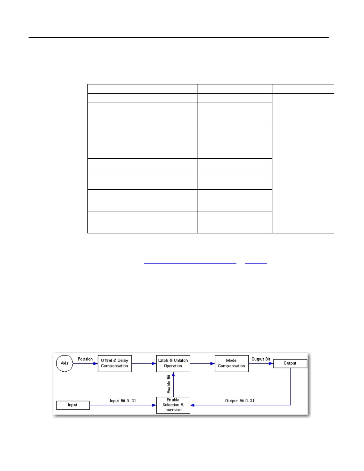
The following diagram shows the effect of the output compensation on the
relationships between the axis, input, and output
Compensation
 Loading...


