Multi-Axis Coordinated Motion Instructions
354 Rockwell Automation Publication MOTION-RM002H-EN-P-February 2018
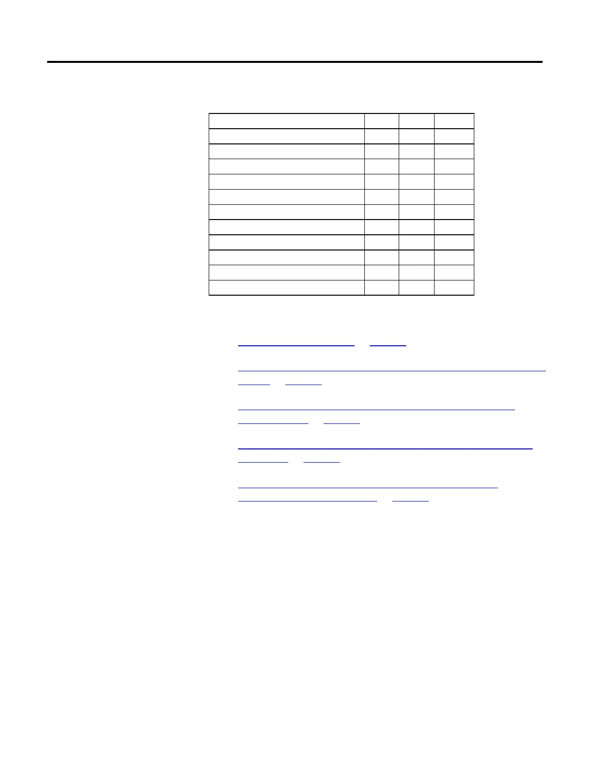
The following table shows the bits status at the transition points.
Bit TP1 TP2 TP3
Move1.DN T T T
Move1.IP T F F
Move1.AC T F F
Move1.PC F T T
Move2.DN T T T
Move2.IP T T F
Move2.AC F T F
Move2.PC F F T
cs1.MoveTransitionStatus F F F
cs1.MovePendingStatus T F F
cs1.MovePendingQueueFullStatus T F F
See also
Choose a Termination Type on page 500
Speed, Acceleration, Deceleration, and Jerk Enumerations for Coordinated
Motion on page 489
Status Bits for Motion Instructions when (MCLM, MCCM) when
MDCC is Active on page 496
Input and Output Parameters Structure for Coordinate System Motion
Instructions on page 511
Changing Between Master Driven and Time Driven Modes for
Coordinated Motion Instructions on page 499
This information applies to the CompactLogix 5370, ControlLogix 5570,
Compact GuardLogix 5370, GuardLogix 5570, Compact GuardLogix 5380,
CompactLogix 5380, CompactLogix 5480, ControlLogix 5580, and GuardLogix
5580 controllers. Controller differences are noted where applicable.
The Master Driven Coordinated Control (MDCC) instruction defines a
Master:Slave relationship between a Master Axis and a Slave Coordinate System.
Master Driven Coordinated
Control (MDCC)
 Loading...


