Multi-Axis Coordinated Motion Instructions
Rockwell Automation Publication MOTION-RM002H-EN-P-February 2018 463
Coordinate System
The Coordinate System operand specifies the set of motion axes that define the
dimensions of a Cartesian coordinate system. For this release the coordinate
system supports up to three (3) primary axes. Only the axes configured as primary
axes (up to 3) are included in the coordinate velocity calculations.
Motion Control
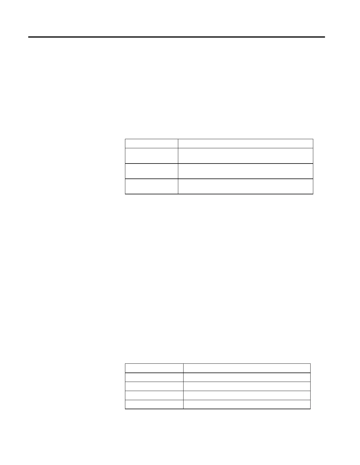
The following control bits are affected by the MCSR instruction.
Mnemonic Description
.EN (Enable) Bit 31 The Enable bit is set when the rung transitions from false to true. It resets when
the rung transitions from true to false.
.DN (Done) Bit 29 The Done bit sets when the coordinated shutdown reset is successfully initiated.
It resets when the rung transitions from true to false.
.ER (Error) Bit 28 The Error bit sets when the reset of the coordinated shutdown fails to initiate. It
resets when the rung transitions from false to true.
This is a transitional instruction:
• In relay ladder, toggle the Rung-condition-in from false to true each time
the instruction should execute.
• In structured text, condition the instruction so that it only executes on a
transition.
Affects Math Status Flags
No
Major/Minor Faults
None specific to this instruction. See Common Attributes in operand-related
faults.
Execution
Ladder Diagram
Condition/State Action Taken
Prescan The .EN, .DN, .ER, and .IP bits are cleared to false.
Rung-condition-in is false The .EN bit is cleared to false if either the .DN or .ER bit is true.
Rung-condition-in is true The .EN bit is set to true and the instruction executes.
Postscan N/A