D7024 | Operation and Installation Guide | 3.0 Installation and Setup
14 Bosch | 7/05 | 31499J
3.0 Installation and Setup
The shipping box includes:
• One D7024 FACP in a static-resistant bag
• One enclosure with transformer
• One hardware pack
• One enclosure lock, washer, and keys
• Six EOL resistors
The hardware pack includes the hardware needed to
install the control panel in the enclosure.
3.1 Installing the Enclosure
1. Using the enclosure as a template, mark the top
mounting holes on the mounting surface (Figure 3).
2. Start the mounting screws (not supplied) for these
two holes first. Slide the enclosure onto these screws
so the screws move up into the thinner section of
the holes. Then tighten the screws.
3. Screw the remaining two screws into either set of
bottom mounting holes.
4. Knock out the desired wire entrances on the
enclosure.
3.2 Installing the Control Panel
1. Insert the three support posts in the retainer holes
on the enclosure (Figure 3 and Figure 4).
2. Press the 0.125-in. nylon standoffs (P/N: 30503)
into the retainer holes (Figure 3 and Figure 4).
3. Slide the top of the control board into the retainer
tabs (the slots under the top of the frame) so the
control board resets on the posts.
4. Secure the bottom of the control by screwing the
two bottom corners through the support posts and
through to the control board retainer holes
(Figure 4).
5. When the control board is installed, use the nuts to
connect the ground wire between the door and the
enclosure. Use the second ground wire to connect
the AC power ground. Both grounds connect to the
enclosure’s stud to the left of the circuit board.
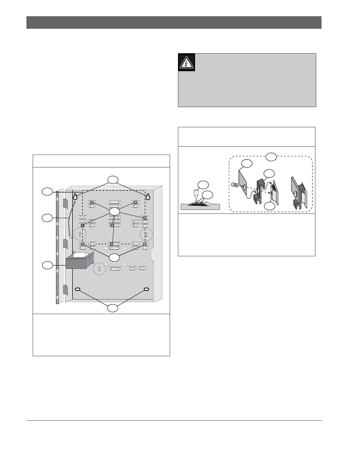
Figure 3: Installing the Enclosure
1 – Control panel location
2 – Ground wire
3 – Transformer
4 – Mounting holes (4)
5 – Standoff retainer holes (6)
6 – Support post retainer holes (2)
4
4
3
2
6
5
1
The D7024 Control Board is static sensitive.
Touch ground before handling the control
board to discharge any static electricity in
your body. For example, run the ground wire
to the enclosure before handling the control
board. Continue touching the enclosure while
installing the control board.
Figure 4: Installing the Standoff and Support
Post
1 – 0.125-in. nylon standoff
2 – Retainer holes (2)
3 – Support post assembly
4 – Corner of circuit board
5 – Support post
6 – Retainer hole in enclosure
4
=
1
2
6
5
3

 Loading...


