D7024 | Operation and Installation Guide | 4.0 Control Panel Terminal Connections
16 Bosch | 7/05 | 31499J
4.0 Control Panel Terminal
Connections
Refer to Figure 5 through Figure 10 when connecting the
control panel terminal.
Incorrect connections can cause damage to
the equipment and personal injury.
Before servicing the equipment, remove all
power including the transformer, battery, and
telephone lines.
Do not use shared cable for option bus, tele-
phone, or NAC wiring.
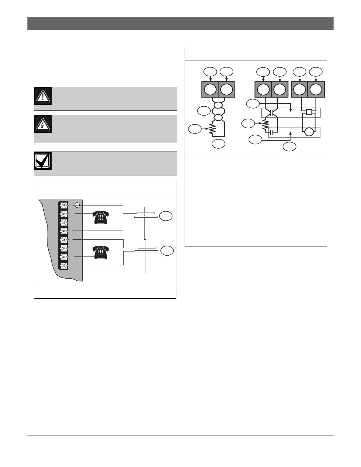
Figure 5: Telephone Line Wiring
1 – Phone Line 1 (supervised)
2 – Phone Line 2 (supervised)
2
1
R2
HR2
HT2
T2
R1
RH1
TH1
T1
Figure 6: Typical Fire Wiring
1 – Input
2 – Loop power +
3 – Smoke detector
4 – EOL resistor
5 – Typical two-wire smoke detector wiring
(supervised). Refer to the D7022 Series, D7024
Smoke Detector Compatibility List (P/N: 34445)
for a list of compatible two-wire smoke detectors.
6 – Smoke power -
7 – Smoke power +
8 – D275 EOL relay
9 – Typical four-wire smoke detector wiring. For
example, a D285 in a D292 Base.
21
2
1
6 7
5
3
9
3
8
4
Z- LP+
SMK
-
SMK
+
Z- LP+
S
S
4

 Loading...


