D7024 | Operation and Installation Guide | 2.0 Overview
Bosch | 7/05 | 31499J 7
2.2 On-board Conventional Points
All on-board points and points implemented with the
D7034 work with two- or four-wire detectors. The
system has an optional alarm verification feature
(Ta b l e 1 ).
All onboard points, and points implemented with the
D7034 Four Point Expander, are continuously
monitored for detectors signaling a dirty condition using
the Bosch Security Systems Chamber Check and
CleanMe protocol. To prevent nuisance reports, there is
a 2-min delay before a dirty detector is annunciated, and
a 6-min delay after the detector restores from the dirty
condition before the control panel restores the
condition.
2.3 Off-board Addressable Points (with
D7039 Multiplex Expansion Module)
The D7039:
• adds two Class “B”, Style 4 signaling line circuits
(SLCs)
• individually supervises each point for proper
connection to the common bus. When more than
ten points are troubled, up to ten troubles are shown
for each bus, and the balance of the troubles is
indicated by a common bus failure message.
• can set response time to fast, or programmed from 1
to 89 sec.
SLC input points are implemented with a D7042 Eight
Input Remote Module.
2.4 Enclosure Housing
The standard enclosure is manufactured from 18 Ga.,
cold-rolled steel and measures 21 in. (53 cm) high, 15 in.
(38 cm) wide, 4 in. (11 cm) deep.
This enclosure includes a keyed lock. The LEDs and
LCD are visible through the door.
2.5 Remote LCD Keypads
• Maximum number: 4 D7033s
• Wiring requirements: Refer to Refer to Section 4.2
Option Bus Wiring Requirements on page 19.
2.6 Remote LED Annunciators
• Maximum number: 8 D7030s.
• Wiring requirements: Refer to Section 4.2 Option Bus
Wiring Requirements.
For flexible configuration, LED annunciators show
output zone information rather than point information.
The first installed annunciator, the one with the lowest
number address on the bus, shows Zones 1 to 8 on the
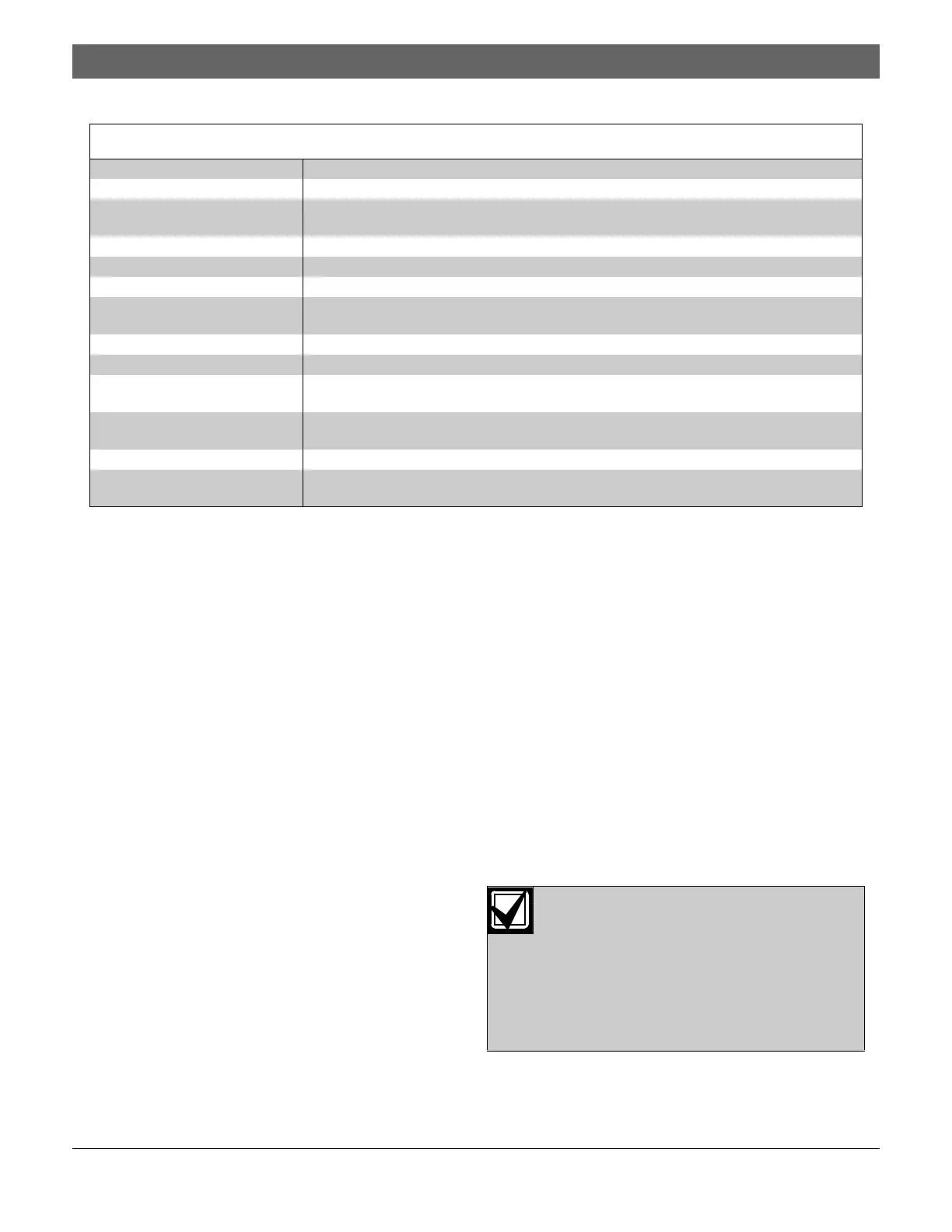
Table 1: On-board Conventional Points
Number of Two-wire Zones Four zones, expandable to eight using a D7034 Expander
Type of Circuit Class “B”, Style B. Use a D7014 Class “A” Zone Converter to convert to Class “A”, Style D
as needed
End-of-Line (EOL) Resistor 2.21 kΩ (P/N: 25899), UL listed
Supervisory Current 8 mA to 20 mA
Required Current for Alarm 25 mA
Maximum Short Circuit Cur-
rent
44 mA
Maximum Line Resistance 150 Ω
Circuit Voltage Range 20.4 VDC to 28.2 VDC
Maximum Number of
Detectors for each Zone
20, two-wire
Total Detector Standby
Current
3 mA, maximum
Response Time Either fast (500 ms) or programmable (from 1 to 89 sec)
Dirty Detector Monitoring Implements Bosch Security Systems Chamber Check™ and CleanMe™ protocol to monitor
conventional loops for dirty detectors. CleanMe™ is a Trademark of SLC Technologies Inc.
Connect all option bus devices to the same
bus, either Bus A or Bus B. Do not connect
some devices to Bus A Terminals YA and GA,
and connect others to Bus B Terminals YB
and GB. Power Terminals RA and RB and
Ground Terminals RA and RB can be con-
nected interchangeably to either set of termi-
nals.

 Loading...


