D7024 | Operation and Installation Guide | 5.0 System Operation
Bosch | 7/05 | 31499J 25
5.3 Keypads
5.3.1 Built-in Keypad
The keypad built into the control panel is an
alphanumeric LCD keypad. It has a two-line by 16-
character display to provide information on various
control panel functions. Generally, the first line shows
common system status information; the second line
describes specific devices that might be relevant to the
current system status.
Ta b l e 12 describes the LEDs and keys on the built-in
keypad.
When keys are being pressed, the display shows the
current action on the first line, while showing rotating
menu choices on the second line. A built-in sounder is
used to annunciate keystroke entries and as a warning
device.
For Abbreviations on Panel Display, refer to Section 11.0
Appendix B: D7024 Control Panel Display Messages on
page 66.
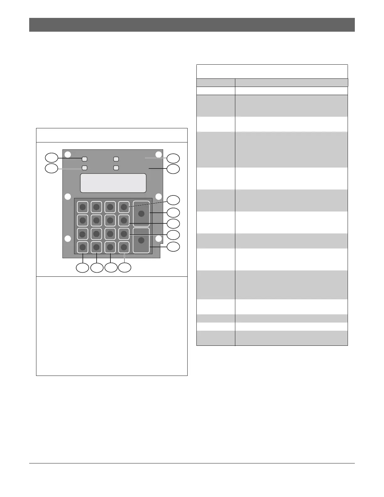
Figure 14: Built-in Keypad
1 – Power LED
2 – Alarm LED
3 – Trouble LED
4 – Silenced LED
5 – DRILL] key
6 – SILENCE] key
7 – [DISABLE] key
8 – [TEST] key
9 – RESET] key
10 –[HISTORY] key
11 –[#/ C M D ] key
12 –[0/PROG] key
13 –[*/ C LEAR ] key
21 3
4 5 6
7 8 9
#
Cmnd
0
Prog
*
Clear
Disable
Drill
Test
History
Reset
Silence
Trouble
Silenced
Power
Alarm
5
6
9
11 10
1
2
3
4
8
7
1213
Table 12: LEDs and Keys
LED or Key Definition
Power LED
(green)
Lights when the AC power is present, and
flashes when the D7024 operates from bat-
tery power.
Alarm LED
(red)
Lights when the system registers an alarm
and the alarm is not reset.
Trouble LED
(yellow)
Lights when the system detects a problem
with its wiring or internal circuitry. Flashes
while Programming Mode is active, and
when inputs are not active (such as during a
smoke power rest or an alarm verification.
Silenced
LED
(yellow)
Lights when the user manually silenced an
alarm or trouble condition. Turns off when
the condition that silenced is corrected.
[DRILL] Manually activates the NACs. Creates a His-
tory Log entry and can be optionally
reported to the central station.
[SILENCE] Quiets the bells and sirens for an alarm or
trouble condition only if the system is config-
ured to do so.
[DISABLE] Allows the system to disable or enable
inputs, NACs, relays (outputs), and dialer.
[TEST] Allows you to select one of seven Test
Modes. Refer to Refer to Section 5.4 Test-
ing on page 26.
[RESET] Briefly turns off power to the detectors to
reset them, clearing any off-normal condi-
tions. The timing is programmable from 1 to
16 sec.
[HISTORY] Allows you to view the record of system
events.
[#/CMD] Accepts data when in Programming Mode.
[0/PROG] Selects the Programming Mode.
[*/CLEAR] During programming, allows you to exit
menus or the Programming Mode entirely.

 Loading...


