D7024 | Operation and Installation Guide | 4.0 Control Panel Terminal Connections
Bosch | 7/05 | 31499J 19
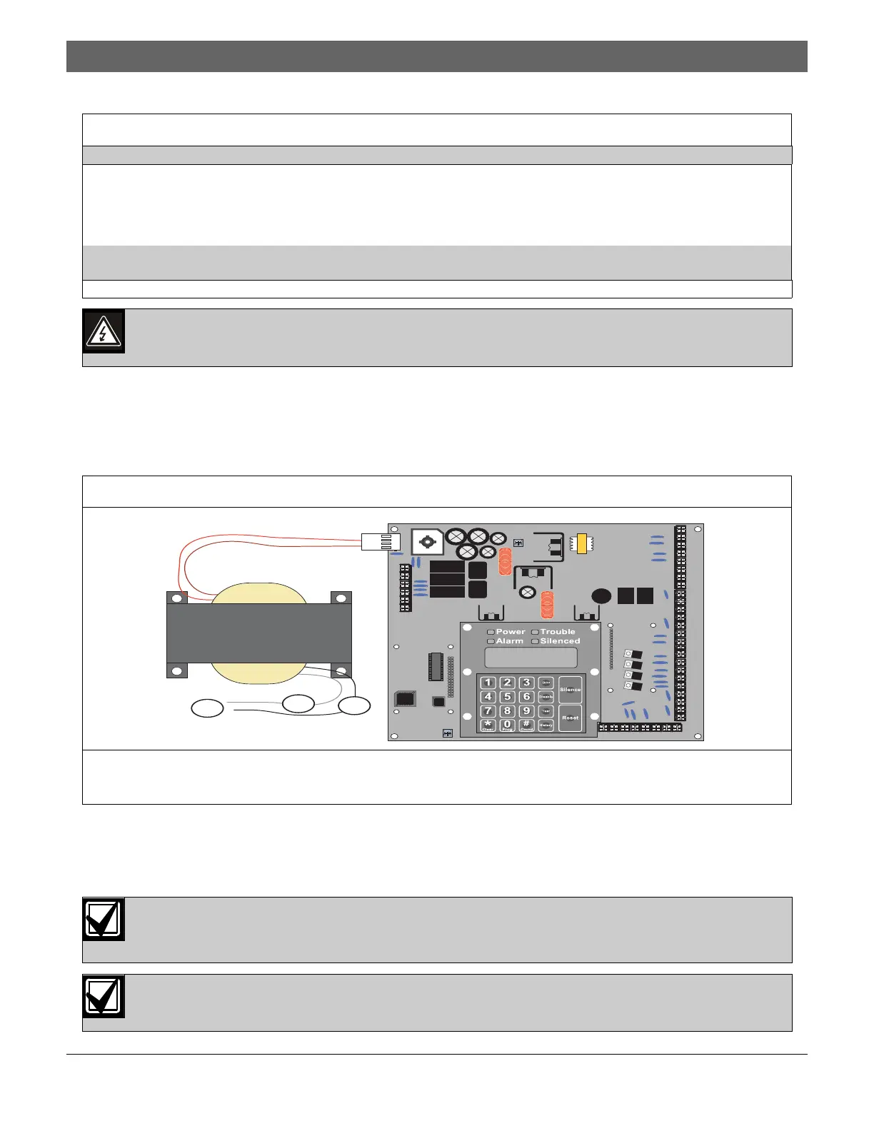
4.1 Power Supply Connections
Use wire nuts to connect the primary side of the transformer, with the black and white wires, to the 120 V, 60 Hz
dedicated circuit breaker. Connect the earth ground to the threaded ground stud on the left side of the enclosure
(Figure 11).
4.2 Option Bus Wiring Requirements
Use 18 AWG (1.2 mm) or larger wire to connect option bus devices to the FACP. The total length of wire
connected to the option bus terminals must not exceed 4000 ft (1219 m), regardless of the gauge wire used.
Table 8: NACs and Batteries
Notification Appliance Circuit
NAC 1+: +24 V in alarm; ground in standby.
NAC 1-: Ground in alarm; supervisory voltage in standby.
NAC 2+: +24 V in alarm; ground in standby.
NAC 2-: Ground in alarm; supervisory voltage in standby.
Batteries
BAT - and BAT +: Requires two 12 V batteries in series for a combined voltage of 24 V. Charge current equals 1.1 A maximum.
Note: Only use indicating devices listed in the D7024 NAC Compatibility List (P/N: 34950).
Do not short terminals. Shorting terminals can cause an explosion or burn.
Figure 11: Connecting the Transformer to the D7024 Control Board
1 – Primary
2 – White wire
3 – Black wire
1
2
3
Connect all option bus devices to the same bus, either Bus A or Bus B. Do not connect some devices to
Bus A Data Terminals YA or GA and some to Bus B Terminals YB or GB. Power Terminals RA and RB, and
Ground Terminals BA and BB can be connected interchangeably to either set of terminals.
Do not use shared cable for option bus, addressable points bus, telephone, or NAC wiring.

 Loading...


