D7024 | Operation and Installation Guide | 4.0 Control Panel Terminal Connections
Bosch | 7/05 | 31499J 17
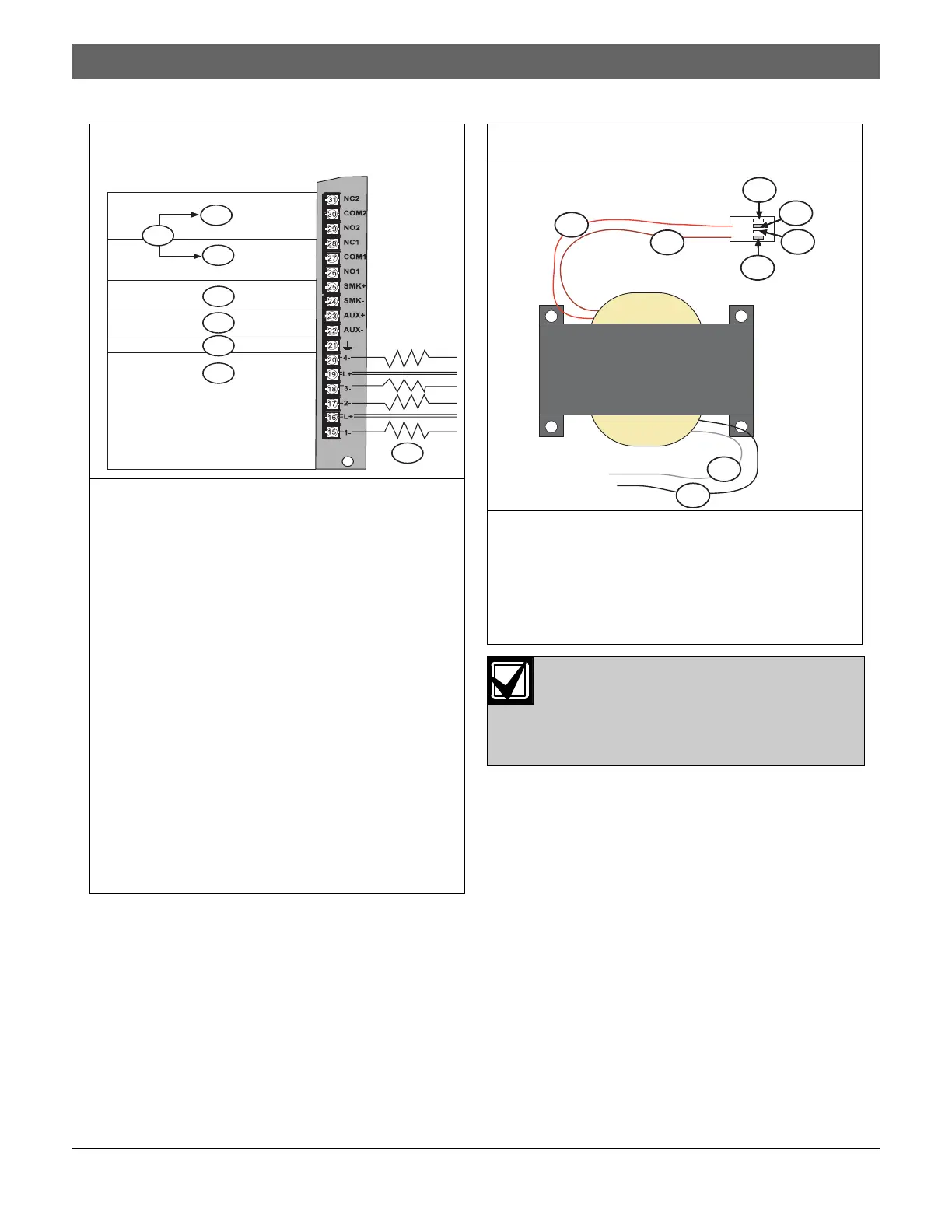
Figure 7: Relay Wiring
1 – Relay 2. Contacts rated at 5 A, 24 V
(unsupervised)
2 – Relay 1. Contacts rated at 5 A, 24 V
(unsupervised)
3 – For connection to listed power limited Class 2 or
Class 3 sources only
4 – Switched (supervised) smoke power: 24 V. 1 A
maximum (filtered). Refer to the D7022 Series,
D7024 Smoke Detector Compatibility List
(P/N: 34445).
5 – Unswitched (unsupervised) auxiliary power:
24 V, 1 A maximum (unfiltered)
6 – Earth ground
7 – Input points 1 to 4 (supervised): Points are
intended for connection to normally-open or
normally-closed alarm contacts. They can also be
used for compatible two-wire smoke detectors.
All EOL resistors are 2.21 k
Ω
(P/N: 25899), UL
Listed. Initiating devices are Class “B”, Style B.
Two-wire compatibility identifier “A.”
8 – Refer to the D7022 Series, D7024 Smoke
Detector Compatibility List (P/N: 34445).
4
6
5
7
2
1
8
3
Figure 8: Transformer (Supervised)
1 – Red wire
2 – Brown wire
3 – NC
4 – AC power 2
5 – AC power 1
6 – White wire
7 – Black wire
All wiring except battery terminal and primary
AC power is power-limited. Separate the pri-
mary AC and battery wires from other wires
by at least 0.25 in. (64 mm). Also tie the wire
to prevent movement.
1
2
4
5
3
7
6
3

 Loading...


