D7024 | Operation and Installation Guide | 4.0 Control Panel Terminal Connections
18 Bosch | 7/05 | 31499J
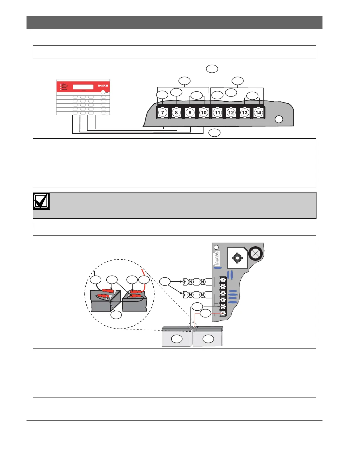
Figure 9: Option Bus (Supervised, Style 4)
1 – Option power (A + B) 500 mA, maximum
2 – Option Bus A
3 – Option Bus B
4 – +12 V
5 – Com
6 – Data
7 – Connect option bus devices to Option Bus A or Option Bus B.
1
2
3
RABAGAYARBBBGBYB
4
5
6
6
4
5
7
1 23
456
789
0
*
#
Clear
Prog
Cmd
Disable
Reset
History
Test
Drill
Silence
Connect all option bus devices to the same bus, either Bus A or Bus B. Do not connect some devices to
Bus A Data Terminals YA or GA and some to Bus B Data Terminals YB or GB. Power Terminals RA and
RB and Ground Terminals BA and BB can be connected interchangeably to either set of terminals.
Figure 10: Backup Battery Wiring
1 – 2.21 k
Ω
EOL, supervised (P/N: 25899)
2 – Black wire
3 – Red wire
4 – Terminal -
5 – Terminal +
6 – Backup Battery #1
7 – Backup Battery #2
1+ 1- 2+ 2-
NAC
-
+
BAT
1
2 34 5
5
7
2
3
6

 Loading...


