2-20
Confidential
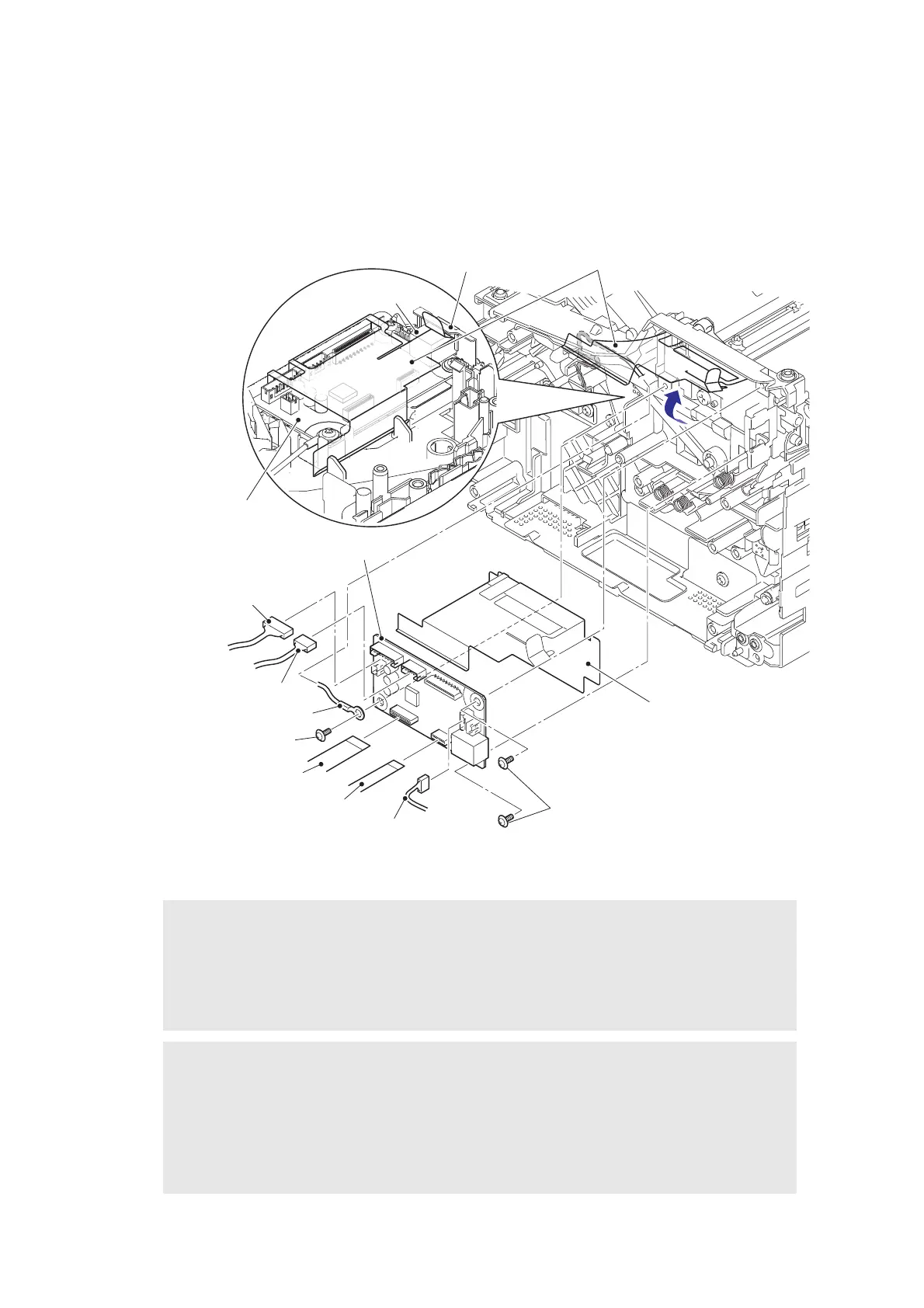
7.10 Main PCB ASSY
(1) Remove the bottom of the main PCB insulation sheet and peel it.
(2) Disconnect all harnesses and flat cables from the main PCB ASSY.
(3) Remove the three taptite cup S M3x6 SR screws to remove the ground harness, the
main PCB ASSY, and the main PCB insulation sheet from the machine.
Fig. 2-18
Harness routing: Refer to “1. Main PCB ASSY / low voltage power supply PCB unit / fuser unit”.
Note:
• Make sure that the main PCB ASSY is secured by screws when connecting or
disconnecting harnesses and flat cables.
• After disconnecting flat cables, check that each cable is not damaged at its end or short-
circuited. When connecting flat cables, do not insert them at an angle. After insertion,
check that the cables are not at an angle.
Assembling Note:
• Insert the main PCB insulation sheet into the gap between the USB connector and the
main shield plate.
• Attach the main PCB insulation sheet and the main PCB ASSY in the order as shown in
the figure above.
• After the assembly, refer to "1. IF YOU REPLACE THE MAIN PCB ASSY" in chapter 3
to configure each setting.
Main PCB insulation sheet
Polygon motor harness
Main PCB
insulation sheet
Taptite cup S M3x6 SR
Paper feed/paper printing position sensor PCB harness
Main shield plate
Taptite cup S M3x6 SR
Laser unit flat cable
Motor encoder
PCB flat cable
Low voltage PCB harness
Ground harness
USB connector
Main PCB ASSY
Main PCB ASSY
 Loading...