2-27
Confidential
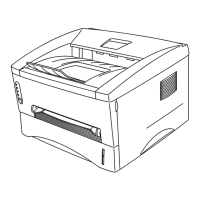
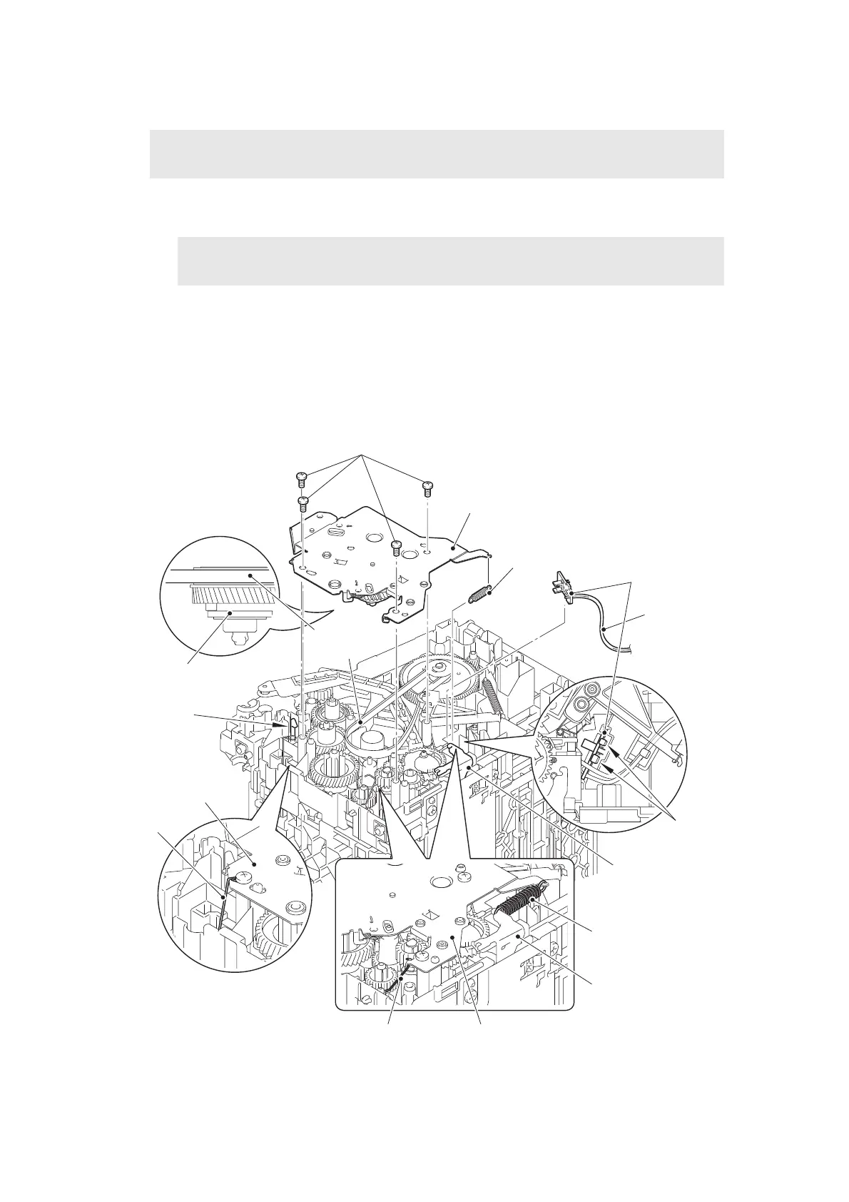
7.16 New toner sensor PCB ASSY
(1) Turn the machine so that the left side of the machine faces upward.
(2) Remove the plate up spring from the plate up plate and the drive sub ASSY.
(3) Remove the four taptite bind B M4x12 screws.
(4) Remove the paper feed FG spring from the drive sub ASSY.
(5)
Release the hook, and remove the drive sub ASSY from the machine by bending the chute
earth spring inward. Remove the motor drive belt from the develop gear of the drive sub ASSY.
(6) Release the new toner sensor PCB harness from the securing fixtures.
(7) Release the two hooks to remove the new toner sensor PCB ASSY.
Fig. 2-27
Harness routing: Refer to “5. New toner sensor PCB ASSY / pick-up solenoid”.
Note:
•
Make sure that the fuser unit is at room temperature to avoid the frame deforming due to heat.
Note:
• Be careful not to uncoil the spring.
Motor drive
belt
Hook
Taptite bind B M4x12
Drive sub ASSY
Plate up spring
New toner sensor
PCB ASSY
Plate up plate
Plate up spring
Plate up plate
Drive sub ASSYPaper feed FG spring
Drive sub ASSY
Chute earth
spring
Develop gear
New toner
sensor PCB
harness
Hooks
 Loading...