Step 9 Rotate the handle to the front of the module (see Callout 1 in the following figure) until it clicks when it reaches the
front of the module.
The module should be fully inserted in the slot and the front of the module should be even with the fronts of all the
other installed modules. The captive screw by the ejector button on the module should be aligned to a screw hole on
the chassis.
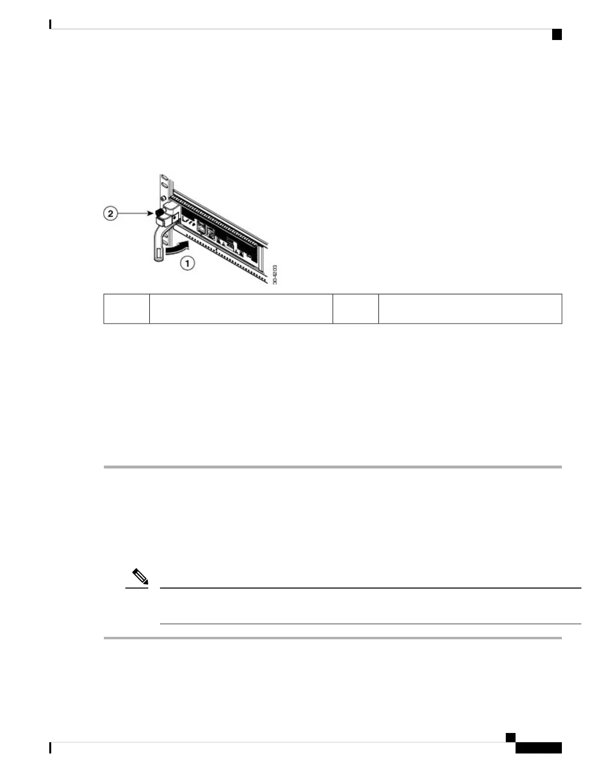
Figure 45: Securing a Supervisor Module to its Slot
Tighten the captive screw to 8 in-lb (0.9 N·m)
of torque.
2Rotate the handle all the way to the front of
the module.
1
Step 10 Screw in the captive screw to secure the module to the chassis (see Callout 2 in the previous figure). Tighten the screw
to 8 in-lb (0.9 N·m) of torque.
Step 11 Verify that the supervisor module LEDs turn on and appear as follows:
• STATUS LED is green.
• SYSTEM LED is green.
• ACTIVE LED is amber or green.
Step 12 Attach the management cable to the MGMT ETH port.
Removing a Supervisor Module
To remove a supervisor module from the chassis, follow these steps:
Before you begin
You need a flat-blade or number 2 Phillips-head screwdriver to loosen or tighten the captive screws on the
supervisor module.
Note
Step 1 Failover the standby supervisor if the switch has two supervisor modules and the supervisor you are removing is
currently active.
Cisco MDS 9700 Series Switches Hardware Installation Guide
115
Installing, Removing, and Verifying Field Replaceable Units
Removing a Supervisor Module
 Loading...