6 NA 1.0
Xbar MAC-Address(es) Serial-Num
--- -------------------------------------- ----------
1 NA JAE1644063E
2 NA JAE1644063I
3 NA JAE16410AS2
4 NA JAE182408ZW
5 NA JAE1644061K
6 NA JAE1710088N
Step 17 Restore the previously saved configurations by using the copy command to copy the configuration file in the USB
drive to the running configuration.
switch(config)# copy usb1:configuration_file_name running-config
If you have not inserted the standby supervisor module until now, do not insert it during this step. Instead,
wait until you complete this procedure before installing the standby supervisor module.
Note
Step 18 Save the configuration in the startup configuration by using the copy running-config startup-config command.
switch(config)# copy running-config startup-config
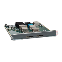
Installing a Switching Module
To install a switching module in the chassis, follow these steps:
Before you begin
When inserting a new line card into a slot, ensure the new line card is of the same model as the existing line
card. If there is a mismatch in the line card models, the line card configurations are removed from the
configuration file.
Note
Step 1 Before installing any modules in the chassis, we recommend installing the chassis in the rack. See the “Installing the
Cisco MDS 9700 Series Switch on a Four-Post Rack or Cabinet” section.
Step 2 Before installing any switching modules, install at least one supervisor module.
Step 3 Choose a slot for the module and verify that there is enough clearance to accommodate any cables or interface equipment
that you want to connect to the module. If possible, place modules between empty slots that contain filler panels.
Step 4 Verify that the captive screws are tightened to 8 in-lb on all modules already installed in the chassis. This ensures that
the EMI gaskets are fully compressed and maximizes the opening space for the module being installed.
Step 5 If a filler panel is installed, remove the two Phillips pan-head screws from the filler panel and remove the panel. To
remove a currently installed module, see Removing a Switching Module, on page 155.
Step 6 Press line card ejector buttons to open both side levers to fully open position.
Step 7 Position the module in the chassis as follows:
a. Align the line card into the chassis card cage slots and push it in slowly. We recommend to push the center of line
card faceplate to push the line card in.
Cisco MDS 9700 Series Switches Hardware Installation Guide
154
Installing, Removing, and Verifying Field Replaceable Units
Installing a Switching Module
 Loading...