The LEDs on the crossbar fabric switching modules indicate the status of the modules. The table shown below
describes the LEDs.
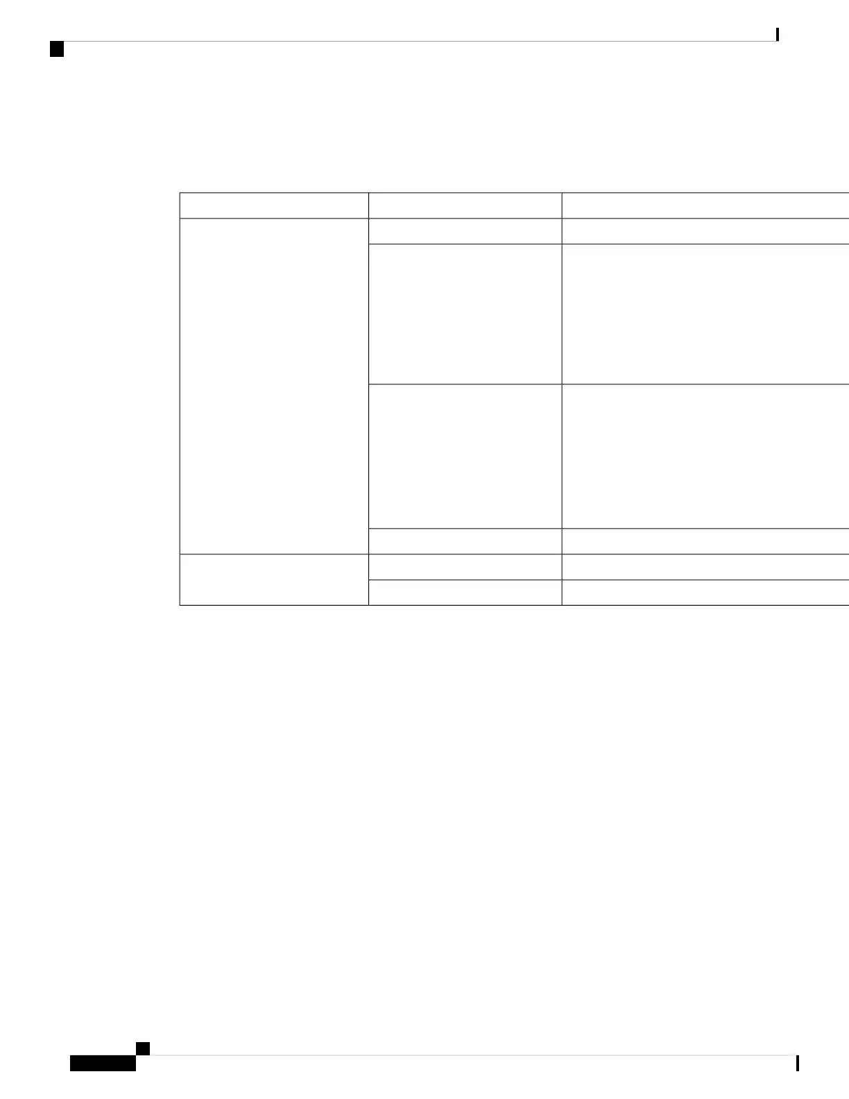
Table 6: Cisco MDS 9718 Director Crossbar Modules LEDs
DescriptionStatusLED
All diagnostics pass. The module is operational (normal initialization sequence).GreenStatus
Indicates one of the following:
• The diagnostic test has failed. The module is not operational because a fault has occurred
during the initialization sequence.
• The inlet air temperature of the system has exceeded the safe operating temperature limits of
the card (a major environmental warning). The card has been shut down to prevent permanent
damage.
Red
Indicates one of the following:
• The crossbar fabric switching module has just been inserted and is booting up.
• An over temperature condition has occurred and the module has powered down.
• The power was turned off with a CLI command.
• The module is resetting and both ejector levers are out.
Blinking Red
The module is not receiving power.Off
The operator has activated this LED to identify this module in the chassis.
Blinking BlueLocater ID
Operator has not flagged this card for identification.Off
Since the crossbar fabric switching modules are located behind the fan modules in the chassis, the LEDs on
the crossbar fabric switching modules are not easily visible from the back of the chassis. So, crossbar fabric
switching module status LEDs are provided on the fan modules as well. Since each fan module covers two
crossbar fabric switching modules, the status LEDs for the two crossbar fabric switching modules are present
on each fan module. If the fan module is removed the status and locator LEDs on crossbar fabric switching
modules will be visible.
When a crossbar fabric switching module needs to be located, the locator LED of the corresponding fan
module needs to be activated, followed by the locator LED of the crossbar fabric switching module, using
the CLIs locator-led fan < fan module number > and locator-led xbar < xbar slot number >. For example,
to locate a crossbar fabric switching module in slot 4, the locator LED of the fan module 2 needs to be activated
followed by the locator LED of the crossbar fabric switching module 4.
Cisco MDS 9710 Director Crossbar Fabric Switching Modules
The Cisco MDS 9710 Director supports up to six crossbar (xbar) fabric switching modules. The crossbar
fabric switching modules DS-X9710-FAB1 and DS-X9710-FAB3 are supported. The crossbar fabric switching
modules are installed vertically at the back of the chassis behind the fan modules.
Crossbar fabric switching modules slots 1 and 2 are behind the fan module slot 1, the crossbar fabric switching
modules slots 3 and 4 are behind the fan module slot 2, and crossbar fabric switching modules slots 5 and 6
are behind the fan module slot 3.
Cisco MDS 9700 Series Switches Hardware Installation Guide
34
Product Overview
Cisco MDS 9710 Director Crossbar Fabric Switching Modules
 Loading...