Link LEDs7Ejector Lever3
FCoE port group. Each port group
consists of 4 ports.
8Status LED4
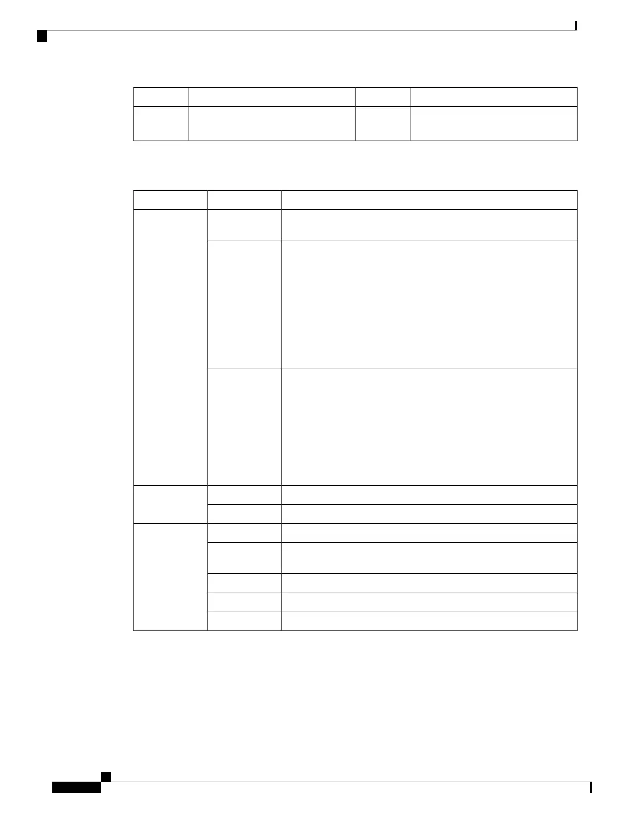
The following table describes the LEDs for the 48-Port 10-Gbps Fiber Channel over Ethernet Module.
Table 13: Cisco MDS 9700 Series 48-Port 10-Gbps FCoE Module LEDs
DescriptionStatusLED
All diagnostics pass. The module is operational (normal initialization
sequence).
GreenStatus
One of the following occurs or occurred:
• The module is booting or running diagnostics (normal initialization
sequence).
• The inlet air temperature of the system has exceeded the maximum
system operating temperature limit (a minor environmental
warning). To ensure maximum product life, you should immediately
correct the environmental temperature and restore the system to
normal operation.
Orange
One of the following occurs:
• The diagnostic test failed. The module is not operational because
a fault occurred during the initialization sequence.
• The inlet air temperature of the system has exceeded the safe
operating temperature limits of the card (a major environmental
warning). The card has been shut down to prevent permanent
damage.
Red
The operator has activated this LED to identify this module in the chassis.
Blinking blueID
This module is not being identified.Off
Link is up.
Solid greenLink
Link is up (traffic on port).Intermittent
blinking green
SFP is not present or Admin is down.Solid orange
A fault condition exists.Blinking orange
The port is not active or the link is not connected.Off
Fan Modules
This section describes the fan modules present in the Cisco MDS 9700 Series Directors.
Cisco MDS 9700 Series Switches Hardware Installation Guide
52
Product Overview
Fan Modules
 Loading...