Service Handbook OEB/OES/OGB/OGS
Check:
When the green LED 42 on the front side of the arrangement module is lit, the
module is operating correctly. (module self-checking).
When the red LED 41 is lit, the arrangement module is defective and must be
replaced. (module self-checking).
LED 41 and 42 see 6.1.5 Positions of the LEDs on the Controls.
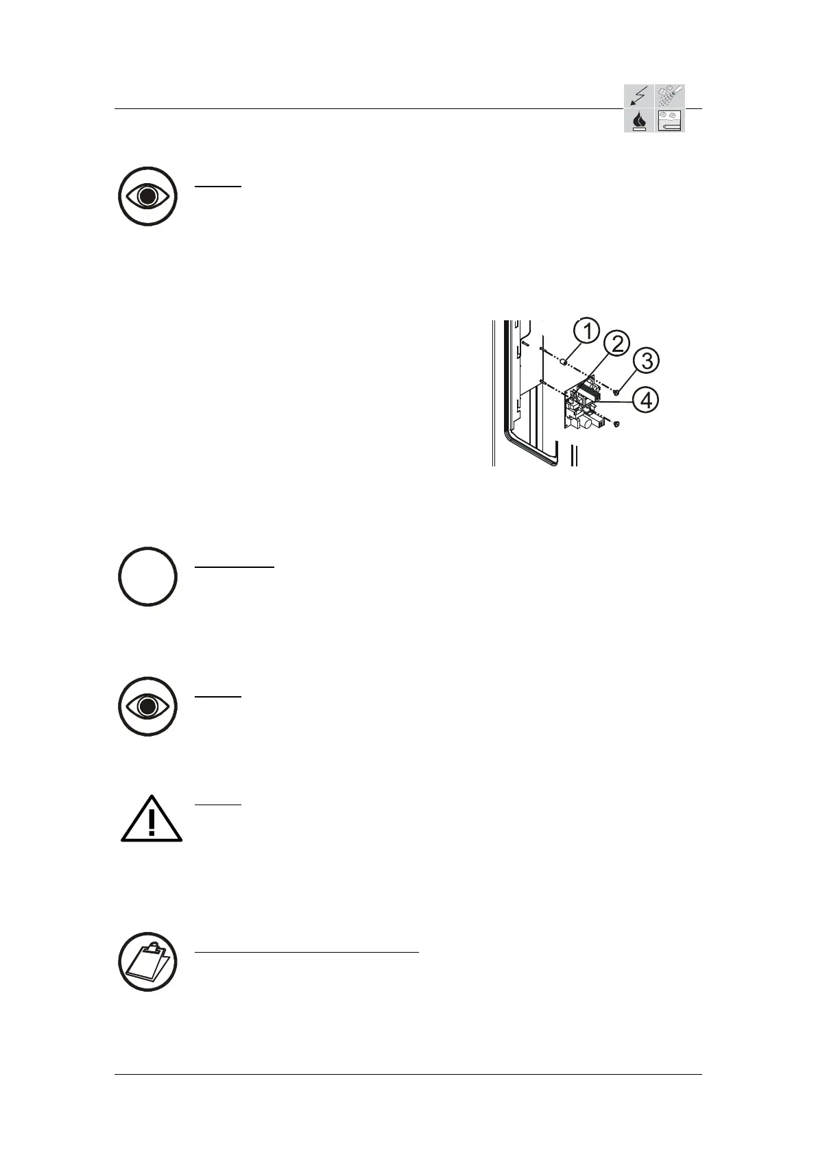
1 = Dist
ancing bolts
2 = Connection for the flat plugs (network connection)
3 = Knurled nuts
4 = Arrangement module
6.1.4 Gas module (GM) removal
i
Information:
Gas module part no.: 5019103
The gas module is the control element for the gas technology in units with
more than two burners (only OGB).
The Gas module is assembled "piggy-back" on the Control module.
Check:
When the green LED 25 on the front side of the gas module is blinking, it is
operating correctly.
LED 25 see 6.1.5 Positions of the LEDs on the Controls.
Safety:
When working on the operation module, make sure that the main power
supply is disconnected (an all-pole isolation switch with a minimum contact
opening of 3mm must be located close to the unit- on site) and ensured
against switching on again.
Close gas supply.
This work should only be performed by a CONVOTHERM trained electrician.
Instructions: Gas module removal
Remove the front plate from operation module and lay it next to unit (see
"6.1.1 Operation module removal").
Unscrew the knurled nuts 6 under the assembly panel 1 from the control
module 4 .
Lift the assembly panel 1 under from out from the holding bolts 7.
AS/11-2011 6_01e_Electronic Control Board installation_c
Page 6 / 8
 Loading...