Service Handbook OEB/OES/OGB/OGS
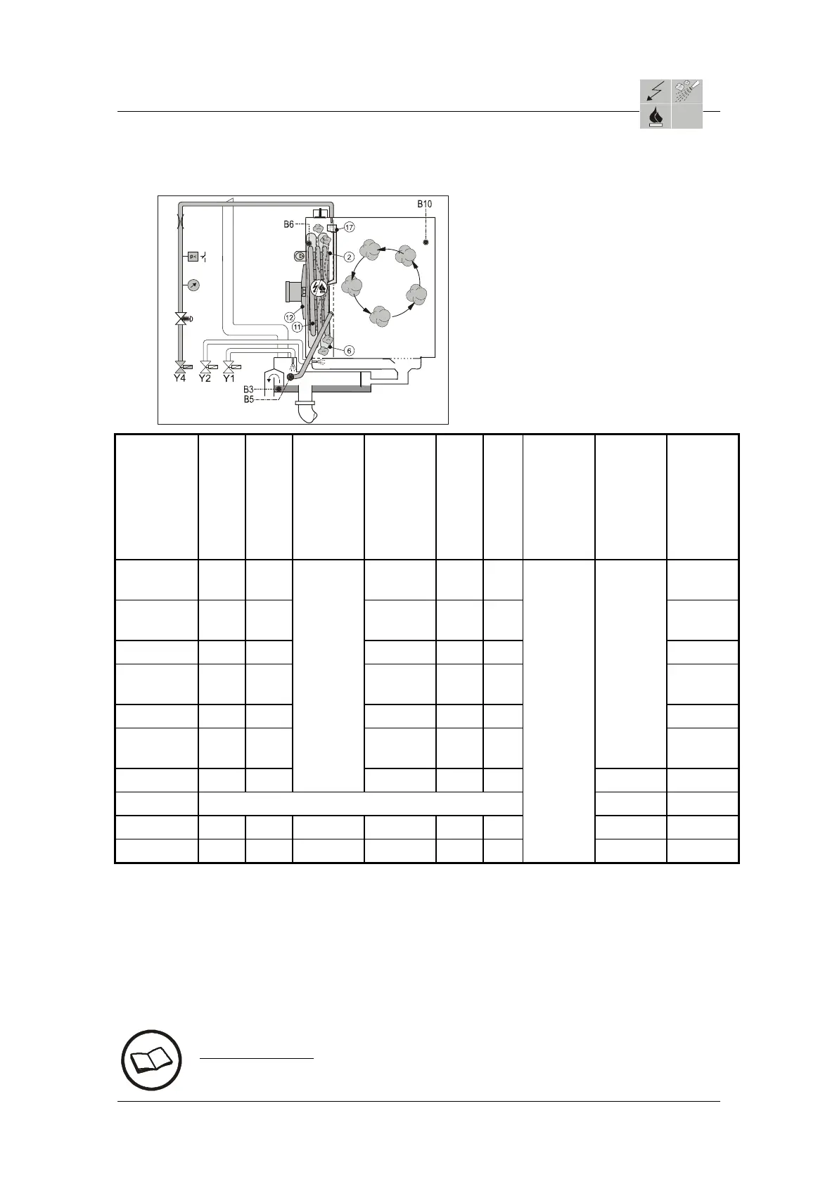
2.5.8b Overview Chart: Processes and Probes in units with direct injection
2 = Fan wheel
6 = Convection heat exchanger
11 = Convection heating
12 = Fan motor
17 = Injection
Convection heating/
Convection burner
Injection
Solenoid valve Y4
Solenoid valve Y1
Fan pulsing
possible
Oven probe B6
Bypass probe B5
Condenser probe
B3
CTC probe B10
(Option)
Solenoid valve Y2
Steaming at
100°C
— x — x x —
Steaming
under 100°C
— x x x — —
Convec-tion
x x — x x x
Steaming
over 100°C
x x — x x —
Convection
x — x x — x
Regene-
ration
x x — x x
Active at
switch-off
criteria
core temp
—
T cooking
x —
Always
active due
to
condenser
rinsing
x x —
active *
x
Cook
Per cooking programme in Cook-Phase *
2
*
5
Hold
x —
As above
x x —
—
*
3
x
Preheating
x —
As above
x x —
Always
active due
to
condenser
rinsing
—*
4
x
* T cooking operates only with CTC.
*
2
active at switch-off criteria core temperature
*
3
not active, because automatic switch-off criteria Time = Continuous.
*
4
not active, because automatic switch-off criteria Time
*5 active with demoisturizing
The cooking programmes T cooking and Cook&Hold are only possible with option core
temperature probe (CTC).
Cross reference:
Service Handbook 5. Trouble shooting and Error Codes Electronic
AS/11-2011 2_05_08e_Overview Chart_c
Page 2 / 2
 Loading...