Service Handbook OEB/OES/OGB/OGS
AS/11-2011 Part-No.: 7016399 6_08e_Motor_fan wheel installation and removal_e
Page 1 / 3
6.8 Motor / Fan Wheel installation and removal
Check:
Uneven browning results
Electrical humming noises
Unit runs mechanically loud
Safety:
When working on the unit, make sure that the main power supply is
disconnected (an all-pole isolation switch with a minimum contact opening of
3mm must be located close to the unit – on site) and ensured against
switching on again.
Information:
Delivery state of a new motor: in a pre-assembled state.
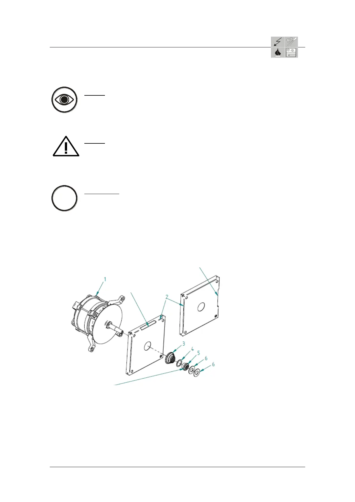
Attention: Pull the 2. flat seal 3 off the motor spindle before assembling the motor 1.
This seal must be set onto the motor spindle from the oven chamber after
assembling the motor.
1 = Motor 4/8pol
2 = Motor sheet P3
3 = Spring for motor shaft
4 = Washer for motor shaft seal
5 = Labyrinth bush P3
6 = Sealing ring motor shaft Viton P3
Position 3, 4 and 5 may not
rotate after installation
Motor sheet with opening to the front
(towards door) fitted for floor appliance
12.20, 20.10, and 20.20
Motor sheet with
opening up mounted for
table top appliances
6.10, 6.20, 10.10, 10.20
Labyrinth bush test on smooth-running turn on the motor shaft. Punctures of the socket fill with
silicone grease OKS 1120 (7004015) and installation.
 Loading...