6.13.4 16-6* Inputs and Outputs
16-60 Digital Input
Range: Function:
0
*
[0 -
1023 ]
View the signal states from the active digital inputs.
Example: Input 18 corresponds to bit no. 5, ‘0’ = no
signal, ‘1’ = connected signal. Bit 6 works in the
opposite way, on = '0', o = '1' (safe stop input).
Bit 0 Digital input term. 33
Bit 1 Digital input term. 32
Bit 2 Digital input term. 29
Bit 3 Digital input term. 27
Bit 4 Digital input term. 19
Bit 5 Digital input term. 18
Bit 6 Digital input term. 37
Bit 7 Digital input GP I/O term. X30/4
Bit 8 Digital input GP I/O term. X30/3
Bit 9 Digital input GP I/O term. X30/2
Bit 10-63 Reserved for future terminals
Table 6.11 Active Digital Inputs
D I T - 3 3
D I T - 3 2
D I T - 2 9
D I T - 2 7
D I T - 1 9
D I T - 1 8
D I T - 3 7
D I X 3 0/4
D I X 3 0/3
D I X 3 0/2
D I X 4 6/ 1 3
D I X 4 6/ 1 1
D I X 4 6/9
D I X 4 6/ 7
D I X 4 6/ 5
D I X 4 6/3
D I X 4 6/ 1
130BA894.10
0
0
0 0 0 0 0 0 0 0 0 0 0 0 0 0 0
Figure 6.21 Relay Settings
16-61 Terminal 53 Switch Setting
Option: Function:
View the setting of input terminal 53.
[0] Current
[1] Voltage
16-62 Analog Input 53
Range: Function:
0 * [-20 - 20 ] View the actual value at input 53.
16-63 Terminal 54 Switch Setting
Option: Function:
View the setting of input terminal 54.
[0] Current
[1] Voltage
16-64 Analog Input 54
Range: Function:
0 * [-20 - 20 ] View the actual value at input 54.
16-65 Analog Output 42 [mA]
Range: Function:
0 * [0 - 30 ] View the actual value at output 42 in mA. The
value shown reects the selection in
parameter 6-50 Terminal 42 Output.
16-66 Digital Output [bin]
Range: Function:
0 * [0 - 15 ] View the binary value of all digital outputs.
16-67 Pulse Input #29 [Hz]
Range: Function:
0 * [0 - 130000 ] View the actual frequency rate on terminal
29.
16-68 Freq. Input #33 [Hz]
Range: Function:
0 * [0 - 130000 ] View the actual value of the frequency
applied at terminal 33 as an impulse input.
16-69 Pulse Output #27 [Hz]
Range: Function:
0 * [0 - 40000 ] View the actual value of pulses applied to
terminal 27 in digital output mode.
16-70 Pulse Output #29 [Hz]
Range: Function:
0 * [0 - 40000 ] View the actual value of pulses at terminal 29
in digital output mode.
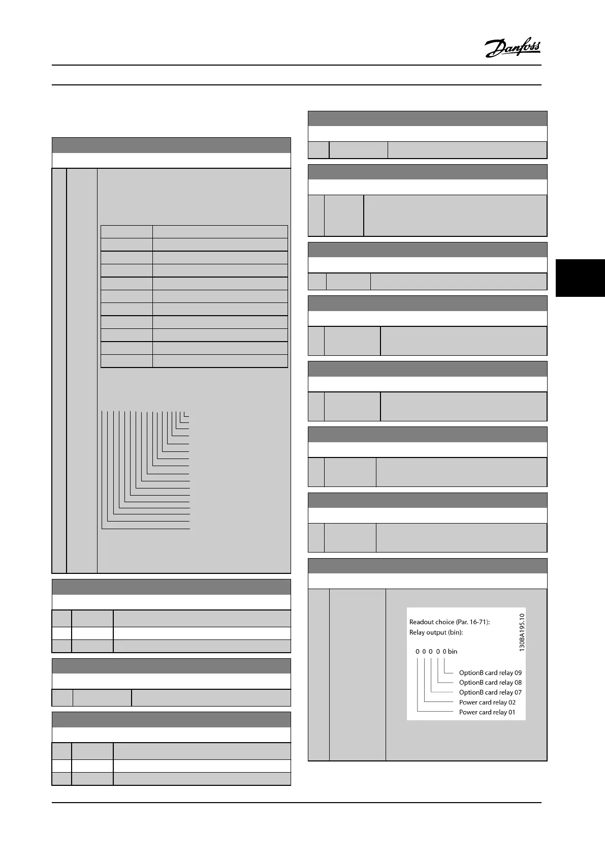
16-71 Relay Output [bin]
Range: Function:
0 * [0 - 511 ] View the settings of all relays.
Figure 6.23 Relay Settings
Parameter Descriptions Operating Instructions
MG34M422 Danfoss A/S © Rev. 2013-07-03 All rights reserved. 109
6
6
 Loading...


