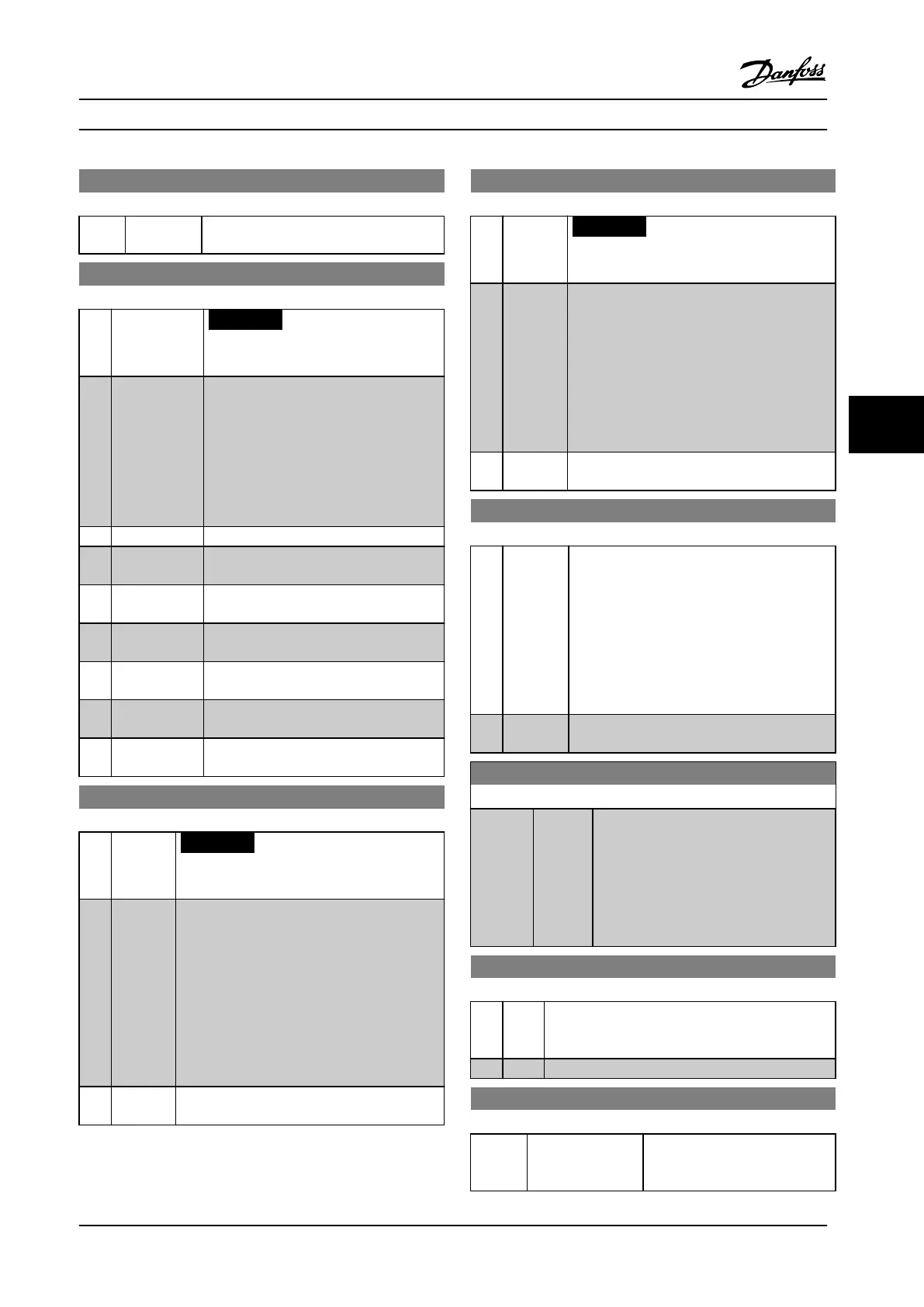
3-14 Preset Relative Reference
Range: Function:
added to the actual reference (X+X*Y/100)
to give the resultant actual reference.
3-15 Reference Resource 1
Option: Function:
NOTICE!
This parameter cannot be adjusted
while the motor is running.
Select the reference input to be used for
the rst reference
signal.parameter 3-15 Reference Resource 1,
parameter 3-16 Reference Resource 2 and
parameter 3-17 Reference Resource 3 dene
up to three dierent reference signals. The
sum of these reference signals denes the
actual reference.
[0] No function
[1] * Analog input
53
[2] Analog input
54
[7] Frequency
input 29
[8] Frequency
input 33
[11] Local bus
reference
[20] Digital
pot.meter
3-16 Reference Resource 2
Option: Function:
NOTICE!
This parameter cannot be adjusted while
the motor is running.
Select the reference input to be used for the
second reference signal. Parameters
parameter 3-15 Reference Resource 1,
parameter 3-16 Reference Resource 2 and
parameter 3-17 Reference Resource 3 dene up to
three dierent reference signals. The sum of
these reference signals denes the actual
reference.
Same options as parameter 3-15 Reference
Resource 1.
[0] * No
function
3-17 Reference Resource 3
Option: Function:
NOTICE!
This parameter cannot be adjusted while
the motor is running.
Select the reference input to be used for the
third reference signal. parameter 3-15 Reference
Resource 1, parameter 3-16 Reference Resource 2
and parameter 3-17 Reference Resource 3 dene
up to three dierent reference signals. The sum
of these reference signals denes the actual
reference.
Same options as parameter 3-15 Reference
Resource 1.
[0] * No
function
3-18 Relative Scaling Reference Resource
Option: Function:
Select a variable value to be added to the xed
value (dened in 3-14 Preset Relative Reference).
The sum of the xed and variable values is
multiplied with the actual reference. This
product is then added to the actual reference
(X+X*Y/100) to give the resultant actual
reference
Same options as parameter 3-15 Reference
Resource 1.
[0] * No
function
3-19 Jog Speed [RPM]
Range: Function:
Size
related*
[ 0 -
par. 4-13
RPM]
Enter a value for the jog speed n
JOG
, which
is a xed output speed. The frequency
converter runs at this speed when the jog
function is activated. The maximum limit is
dened in parameter 4-13 Motor Speed High
Limit [RPM].
See also parameter 3-80 Jog Ramp Time.
3-40 Ramp 1 Type
Option: Function:
Select the ramp type, depending on requirements
for acceleration/deceleration. A linear ramp will give
constant acceleration during ramping.
[0] * Linear
3-41 Ramp Up Time Running (sec)
Range: Function:
5 s min.* [Comp
dependent]
Enter the ramp-up time, i.e. the
acceleration time to reach the
system required motor speed.
Parameter Descriptions Operating Instructions
MG34M422 Danfoss A/S © Rev. 2013-07-03 All rights reserved. 55
6
6
 Loading...


