0-13 Readout: Linked Set-ups
Array [5]
Range: Function:
0 * [0 -
255 ]
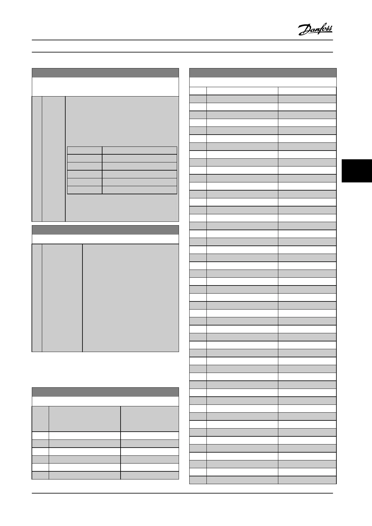
View a list of all the set-ups linked by means of
parameter 0-12 This Set-up Linked to. The
parameter has one index for each parameter set-
up. The parameter value displayed for each index
represents which set-ups are linked to that
parameter set-up.
Index LCP value
0 {0}
1 {1,2}
2 {1,2}
3 {3}
4 {4}
Table 6.3 Example: Set-up 1 and Set-up 2 are
linked
0-14 Readout: Edit Set-ups / Channel
Range: Function:
0 * [-2147483648 -
2147483647 ]
View the setting of parameter 0-11 Edit
Set-up for each of the four dierent
communication channels. When the
number is displayed in hex, as it is in the
LCP, each number represents one channel.
Numbers 1-4 represent a set-up number;
‘F’ means factory setting; and ‘A’ means
active set-up. The channels are, from right
to left: LCP, FC-bus, USB, HPFB1-5.
Example: The number AAAAAA21h means
that the FC bus selected Set-up 2 in
parameter 0-11 Edit Set-up, the LCP
selected Set-up 1 and all others used the
active set-up.
6.2.2 0-2* LCP Display
Dene the display in the Graphical Logic Control Panel.
0-20 Display Line 1.1 Small
Option: Function:
Select a variable for
display in line 1, left
position.
[0] None
[953] Probus Warning Word
[1005] Readout Transmit Error Counter
[1006] Readout Receive Error Counter
[1007] Readout Bus O Counter
[1013] Warning Parameter
0-20 Display Line 1.1 Small
Option: Function:
[1501] Running Hours
[1502] kWh Counter
[1508] Number of Starts
[1509] Number of Auto Resets
[1600] Control Word
[1601] Reference [Unit]
[1602] Reference %
[1603] Status Word
[1605] Main Actual Value [%]
[1609] Custom Readout
[1610] Power [kW]
[1611] Power [hp]
[1612] Motor Voltage
[1613] Frequency
[1614] Motor current
[1615] Frequency [%]
[1616] Torque [Nm]
[1617] Speed [RPM]
[1618] Motor Thermal
[1619] KTY sensor temperature
[1620] Motor Angle
[1622] Torque [%]
[1630] DC Link Voltage
[1632] Brake Energy /s
[1633] Brake Energy /2 min
[1634] Heatsink Temp.
[1635] Inverter Thermal
[1636] Inv. Nom. Current
[1637] Inv. Max. Current
[1638] SL Controller State
[1639] Control Card Temp.
[1650] External Reference
[1651] Pulse Reference
[1652] Feedback[Unit]
[1653] Digi Pot Reference
[1654] Feedback 1 [Unit]
[1655] Feedback 2 [Unit]
[1660] Digital Input
[1661] Terminal 53 Switch Setting
[1662] Analog Input 53
[1663] Terminal 54 Switch Setting
[1664] Analog Input 54
[1665] Analog Output 42 [mA]
[1666] Digital Output [bin]
[1667] Freq. Input #29 [Hz]
[1668] Freq. Input #33 [Hz]
[1669] Pulse Output #27 [Hz]
[1670] Pulse Output #29 [Hz]
[1671] Relay Output [bin]
[1672] Counter A
Parameter Descriptions Operating Instructions
MG34M422 Danfoss A/S © Rev. 2013-07-03 All rights reserved. 49
6
6
 Loading...


