61
68
69
39
42
50
53
54
55
12
13
18
19
27
29
32
33
20
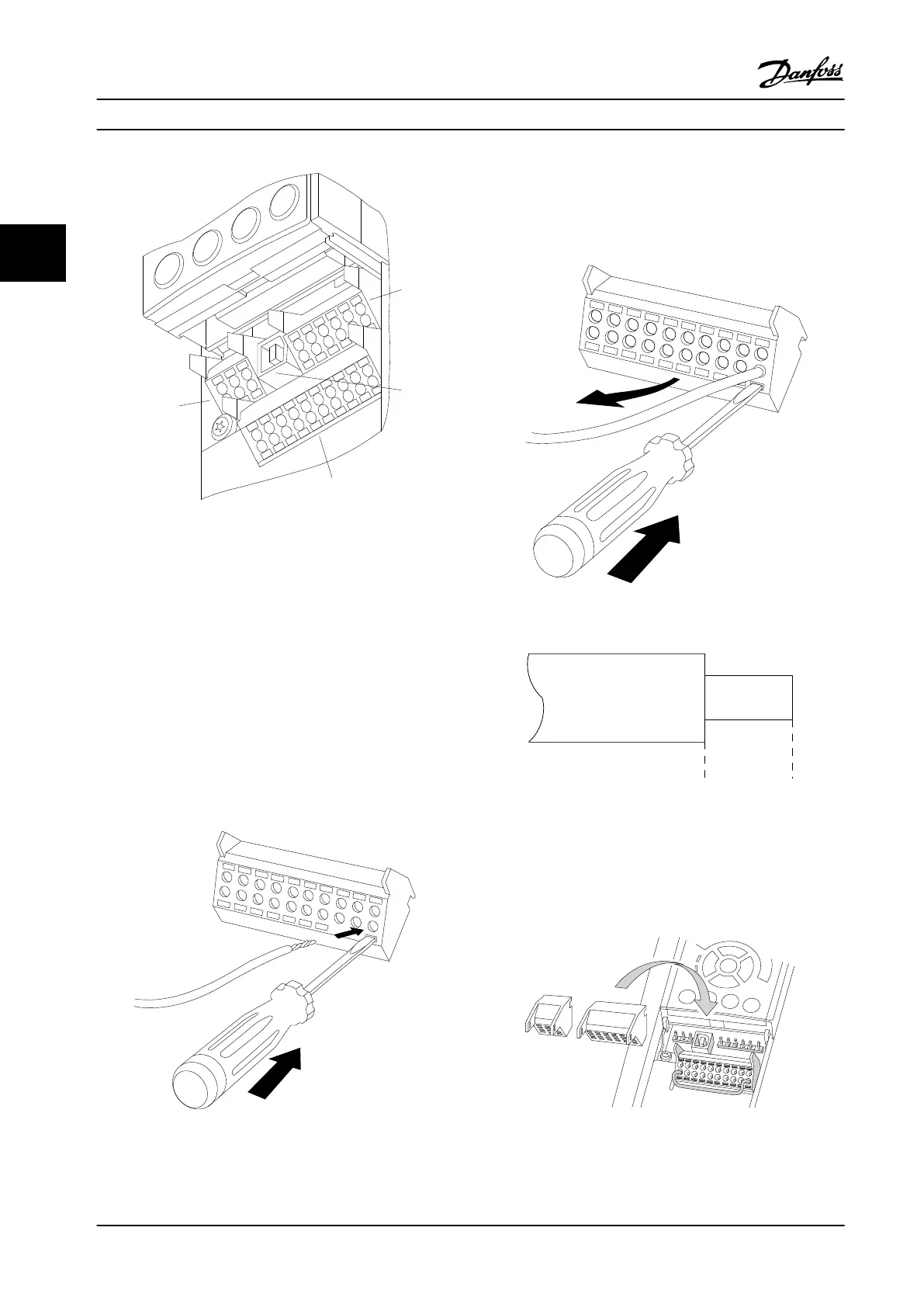
Figure 3.18 Control Terminals
1. 10 pole plug digital I/O
2. 3 pole plug RS-485 Bus
3. 6 pole analog I/O
4. USB Connection
To mount the cable to the terminal:
1. Strip isolation of 9-10 mm.
2. Insert a screwdriver in the square hole.
3. Insert the cable in the adjacent circular hole.
4. Remove the screwdriver. The cable is now
mounted to the terminal.
Figure 3.19 Mounting the Cable
To remove the cable from the terminal:
1. Insert a screwdriver in the square hole.
2. Pull out the cable.
Figure 3.20 Removing the Cable
130BA150.10
9 - 10 mm
(0.37 in)
Figure 3.21 Stripping the Cable
3.3.10 Basic Wiring Example
1. Mount terminals from the accessory bag to the
front of the frequency converter.
Figure 3.22 Mounting the Terminals
How to Install
VLT
®
Compressor Drives CDS 302/CDS 303
22 Danfoss A/S © Rev. 2013-07-03 All rights reserved. MG34M422
33
 Loading...


