The BASIC Cascade/Pack Controller is used for up to 3
compressors to control up to two on/o compressors
together with one variable speed compressor. The capacity
control is typically based on suction pressure feedback, but
it could also be e.g. a cold room temperature.
Fixed Lead Compressor
The BASIC Pack Controller allows the frequency converter
to control up to 3 compressors using the frequency
converter's two built-in relays. The variable compressor
(lead) is connected directly to the frequency converter,
while 2 bilt-in relays control the other 2 compressors.
NOTICE!
Only one xed speed compressor can be controlled with
the built-in relays. To control two xed compressors, an
extra relay is needed via the MCB 105 Relay Option.
Bandwidth Management
In pack control systems, to avoid frequent switching of
xed speed compressors, the desired system load is kept
within a bandwidth rather than at a constant level. The
Staging Bandwidth provides the required bandwidth for
operation. When a large and quick change in system load
occurs, the Override Bandwidth overrides the Staging
Bandwidth to prevent immediate response to a short
duration load change. An Override Bandwidth Timer can
be programmed to prevent staging until the system load
has stabilised and normal control established.
When the Pack Controller is enabled and running normally,
and the frequency converter issues a trip alarm, staging
and destaging xed speed compressors maintain the
system head pressure. To prevent frequent staging and
destaging and minimise load uctuations, a wider Fixed
Speed Bandwidth is used instead of the Staging
bandwidth.
3.5.2 System Status and Operation
When the pack controller is enabled, the operation status
for each compressor and the pack controller is displayed in
the LCP. Information displayed includes:
•
Compressor Status, is a readout of the status for
the relays assigned to each compressor. The
display shows compressors that are disabled, o,
running on the frequency converter or running
on the mains
•
Pack Status, is a readout of the status for the Pack
Controller. The display shows that the Pack
Controller is disabled, all compressors are o, and
emergency has stopped all compressors, all
compressors are running, xed speed
compressors are being staged/destaged.
•
If a no load need occurs, then destaging ensures
that all xed speed compressors are stopped
individually followed by the variable speed
compressor.
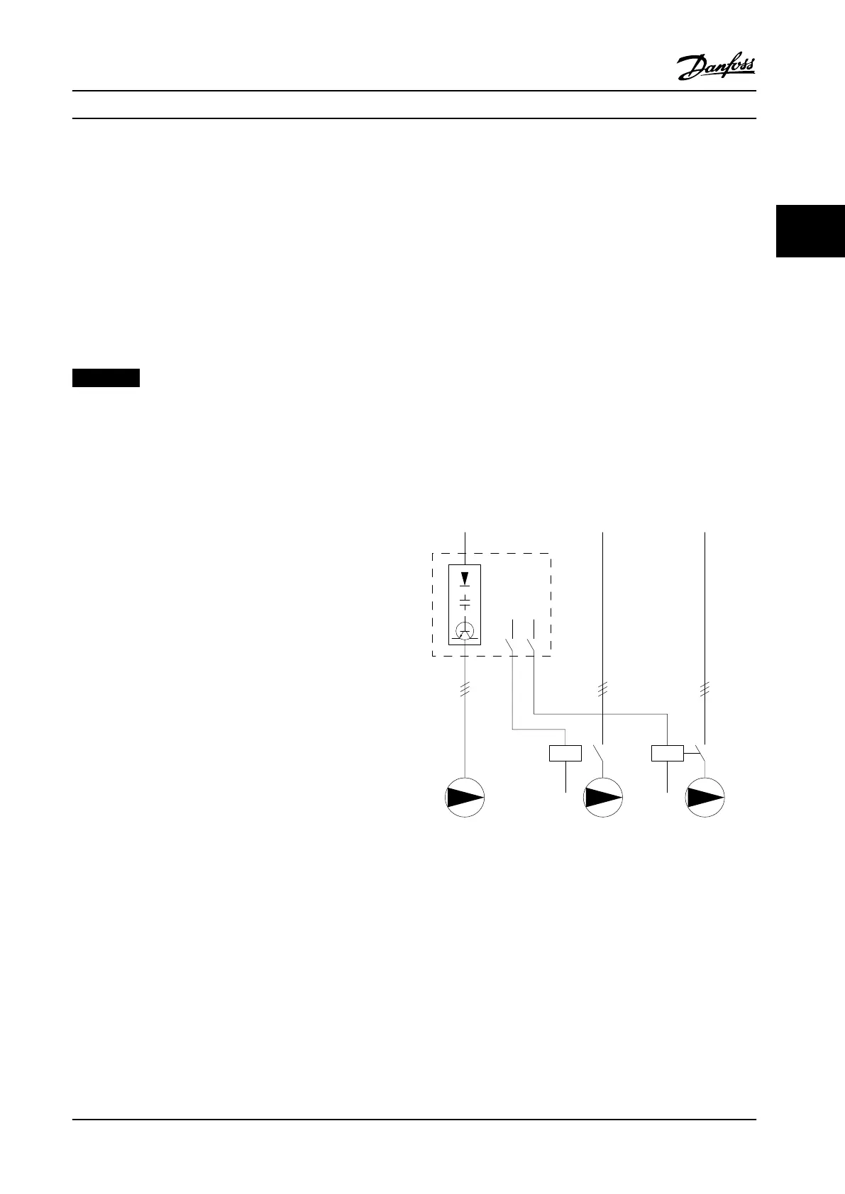
3.5.3 Pack Compressor Wiring Diagram
The wiring diagram shows an example with the built-in
BASIC Cascade Controller with one variable speed
compressor (lead) and two xed speed compressors, a 4-20
mA transmitter and System Safety Interlock.
L1/L2/L3 L1/L2/L3 L1/L2/L3
Power Section
RELAY 2
RELAY from MCB 105
130BD448.10
Figure 3.31 Example with Built-in BASIC Cascade Controller
How to Install Operating Instructions
MG34M422 Danfoss A/S © Rev. 2013-07-03 All rights reserved. 35
3 3
 Loading...


