130BA406.10
61 68 6
39 42 50 53 54 5
03 02 01
06 05 04
A
B
C D
E
F
G
H
I
J K
WARNING:
Risk of Electric Shock - Dual supply
Disconnect mains and loadsharing before service
ISOA0021
Figure 3.4 Enclosures C1 and C2, IP55/66/Type 1/Type 12
99
95
61
68
39
50
53
54
5
42
03
02
01
06
05
04
130BT348.10
Risk of Electric Shock - Dual supply
Disconnect mains and loadsharing before service
WARNING:
RELAY 1
RELAY 2
Figure 3.5 Enclosure C3, IP20/Chassis
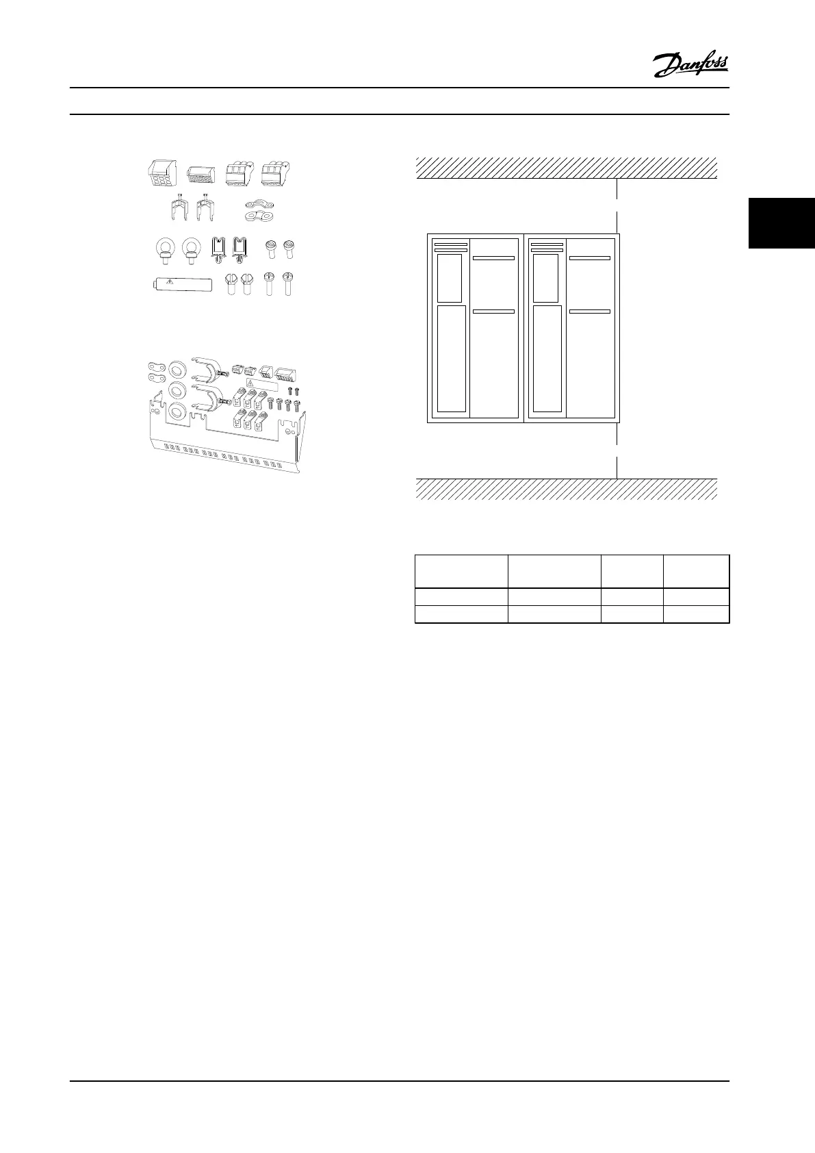
3.2.2 Mechanical Mounting
1. Drill holes in accordance with the measurements
given.
2. Provide screws suitable for the surface on which
the compressor drive should be mounted.
3. Retighten all four screws.
The frequency converter IP20 allows side-by-side instal-
lation. Because of the need for cooling, there must be a
minimum of 7.9 in (200 mm) free air passage above and
below the frequency converter.
The back wall must always be solid. All frequency
converters are equipped with a back metal plate to
guarantee proper heat exchanger ventilation. Never
remove this metal sheet.
Figure 3.6 Clearance
Frame size
A1*/A2/A3/A4/A5
/B1
B2/B3/B4/C
1/C3
C2/C4
a [Inch/mm] 3.3/100 7.9/200 8.9/225
b [inch/mm] 3.3/100 7.9/200 8.9/225
Table 3.2 Air Passage for Dierent Frame Sizes
How to Install Operating Instructions
MG34M422 Danfoss A/S © Rev. 2013-07-03 All rights reserved. 15
3 3
 Loading...


