[85] SL Digital
Output F
See parameter 13-52 SL Controller Action.
The input will go high whenever the Smart
Logic Action [43] Set dig. out. A high is
executed. The input will go low whenever
the Smart Logic Action [37] Set dig. out. A
low is executed.
[122] No alarm The output is high when no alarm is
present.
[123] Start
command
active
The output is high when there is an active
Start command (i.e. via digital input bus
connection or [Hand on] or [Auto on], and
no Stop or Start command is active.
[124] Running
reverse
The output is high when the frequency
converter is running counter clockwise (the
logical product of the status bits ‘running’
AND ‘reverse’).
[125] Drive in hand
mode
The output is high when the frequency
converter is in Hand on mode (as indicated
by the LED light above [Hand on].
[126] Drive in auto
mode
The output is high when the frequency
converter is in Hand on mode (as indicated
by the LED light above [Auto on].
[139] Compressor
Inv. Interlock
Use with cascade controller. Logic will stop
the xed speed compressor and give a
warning.
[140] Compressor
Inv. Interlock
Use with cascade controller. Logic will stop
the xed speed compressor and give a
warning.
[141] Compressor
Inv. Interlock
Use with cascade controller. Logic will stop
the xed speed compressor and give a
warning.
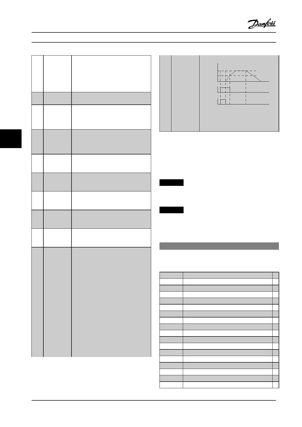
[195] Bypass Valve
Control
The bypass valve control (Digital/Relay
output in the frequency converter) is used
for compressor systems to unload the
compressor during start-up by using a
bypass valve. After the start command is
given the bypass valve will be open until
the frequency converter reaches
parameter 4-11 Motor Speed Low Limit
[RPM]). After the limit has been reached
the bypass valve will be closed, allowing
the compressor to operate normally. This
procedure will not be activated again
before a new start is initiated and the
frequency converter speed is zero during
the receiving of start signal.
Parameter 1-71 Start Delay can be used in
order to delay the motor start. The bypass
valve control principle:
Time
REF
Min
Speed
ON
Time
Time
OFF
ON
OFF
Start
Stop
130BA251.10
Speed
Figure 6.7 Bypass Valve Control
The below setting options are all related to the Cascade
Controller.
Wiring diagrams and settings for parameter, see parameter
group 25-** Cascade Pack Controller or more details.
6.6.5 5-4* Relays (Dry Contacts)
NOTICE!
Relays 7, 8, and 9 are only available if MCB 105 relay
card is installed.
NOTICE!
Relay 1 is dedicated to controlling the solenoid valve.
Parameters for conguring the timing and the output
functions for the relays.
5-40 Function Relay
Array [8] (Relay 1 [0], Relay 2 [1], Relay 7 [6], Relay 8 [7],
Relay 9 [8])
[0] No Operation
[1] Control Ready
[2] Drive Ready
[3] Drive Ready/Remote
[4] Stand-by/No Warning
[5] * Running
[6] Running/No Warning
[8] Run on Ref./No Warning
[9] Alarm
[10] Alarm or Warning
[11] At Torque Limit
[12] Out of Current Range
[13] Below Current, low
[14] Above Current, high
[15] Out of Speed Range
[16] Below Speed, low
[17] Above Speed, high
[18] Out of Feedb. Range
Parameter Descriptions
VLT
®
Compressor Drives CDS 302/CDS 303
68 Danfoss A/S © Rev. 2013-07-03 All rights reserved. MG34M422
6
6
 Loading...


