5.1.4 Indicator Lights
If certain threshold values are exceeded, the alarm and/or
warning LED lights up. A status and alarm text appear on
the control panel. The on LED is activated when the
frequency converter receives mains voltage.
•
Green LED/On: Control section is working.
•
Yellow LED/Warn.: Indicates a warning.
•
Flashing Red LED/Alarm: Indicates an alarm
Figure 5.2 Indicator Lights
5.2 LCP Keys
5.2.1 Function Keys
The control keys are divided into functions. The keys below
the display and indicator lamps are used for parameter set-
up, including choice of display indication during normal
operation.
130BP045.10
Status
Quick
Menu
Main
Menu
Alarm
Log
Figure 5.3 Function Keys
[Status] indicates the status of the frequency converter
and/or the compressor motor. Choose between 3 dierent
readouts by pressing the [Status] key: 5 line readouts, 4
line readouts or Smart Logic Control by pushing [Status]
twice.
Press [Status] to select the display mode or to change back
to Display mode from either Quick Menu mode, Main
Menu mode or Alarm mode. Also press [Status] to toggle
single or double read-out mode.
[Quick Menu] allows quick access to dierent Quick Menus
such as:
Q1 - My Personal Menu
Q2 - Quick Set-up
Q3 – PID Process Loop
Q4 - Compressor Functions
Q5 - Changes Made
Q6 - Loggings
Q7 - Load Prole
Use [Quick Menu] for programming the parameters
belonging to the Quick Menu. It is possible to switch
directly between Quick Menu mode and Main Menu mode.
5.2.2 Navigation Keys
The 4 navigation keys are used to navigate between the
dierent choices available in [Quick Menu], [Main Menu]
and [Alarm Log]. Press the keys to move the cursor.
[OK] is used for choosing a parameter marked by the
cursor and for enabling the change of a parameter and
loggings from Quick Menu.
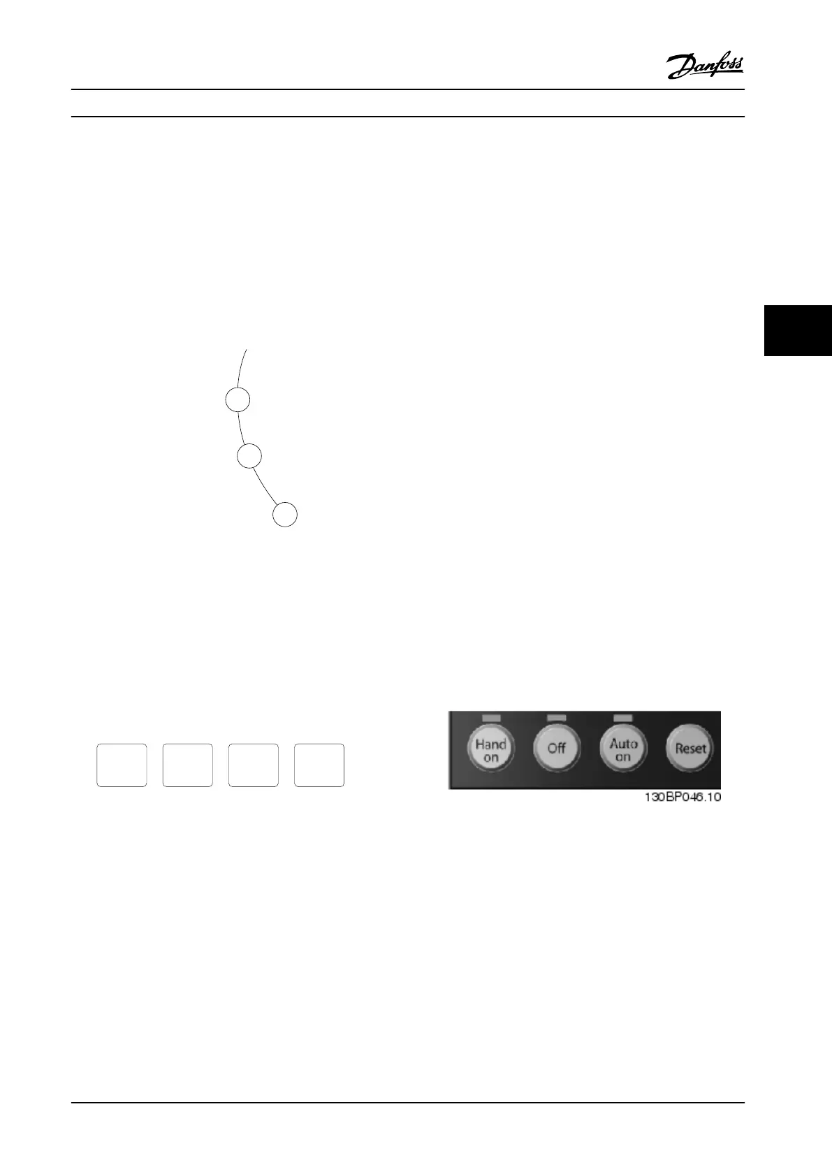
5.2.3 Local Control Keys
Local control keys for local control are found at the bottom
of the control panel.
Figure 5.4 Local Control Keys
How to Program Operating Instructions
MG34M422 Danfoss A/S © Rev. 2013-07-03 All rights reserved. 41
5 5
 Loading...


