Figure 2.2 Jumper between Terminal 12/13 (24 V) and 37
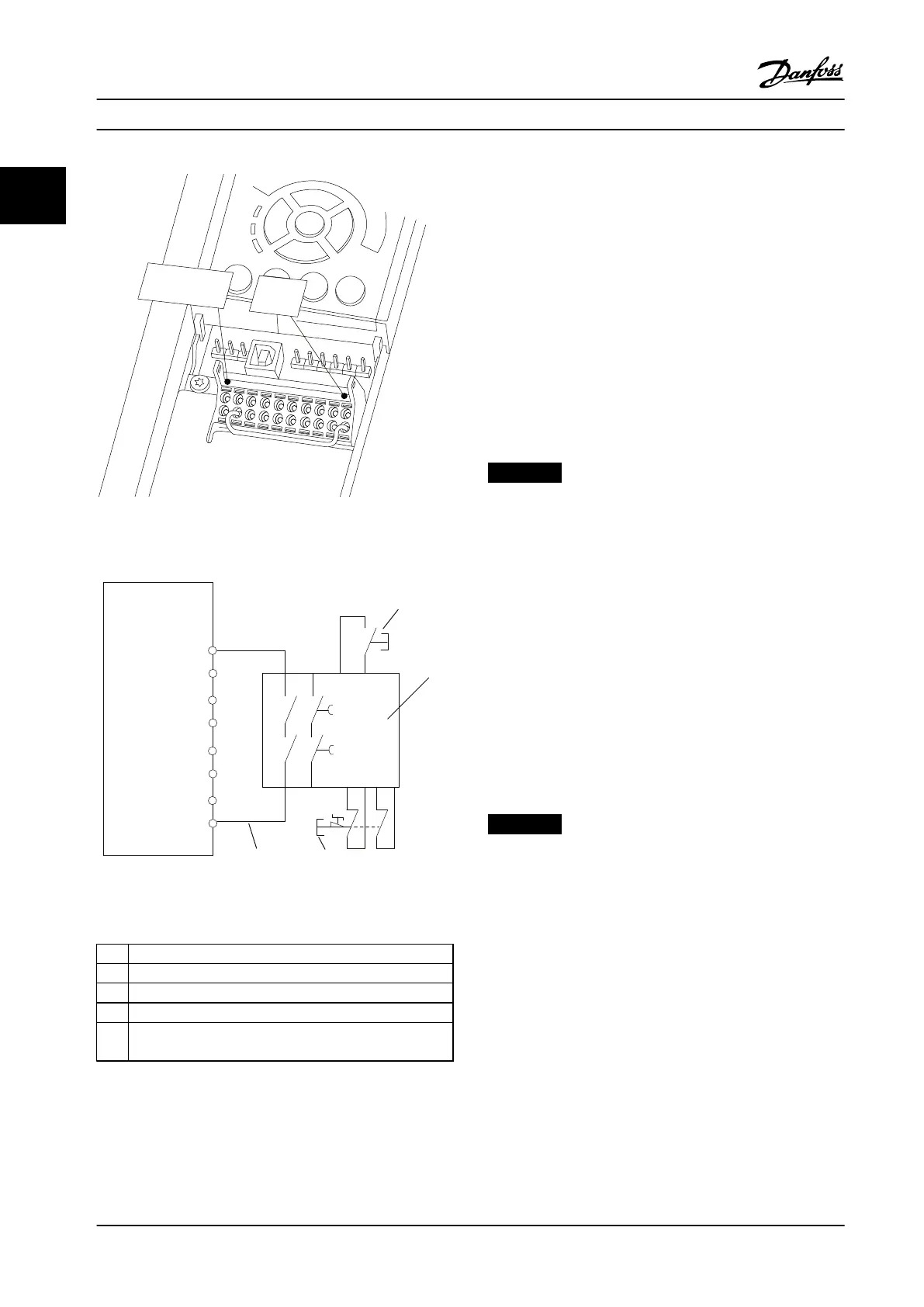
Figure 2.3 Installation to Achieve a Stopping Category 0 (EN
60204-1) with Cat. 3 /PL “d” (ISO 13849-1) or SIL 2 (EN 62061).
1 Frequency converter
2 [Reset] key
3 Safety relay (cat. 3, PL d or SIL2
4 Emergency stop button
5 Short-circuit protected cable (if not inside installation IP54
cabinet)
Table 2.2 Legend to Figure 2.3
Safe Torque O Commissioning Test
After installation and before rst operation, perform a
commissioning test of the installation using Safe Torque
O. Moreover, perform the test after each modication of
the installation.
Example with STO
A safety relay evaluates the E-Stop button signals and
triggers an STO function on the frequency converter in the
event of an activation of the E-Stop button (See Figure 2.4).
This safety function corresponds to a category 0 stop
(uncontrolled stop) in accordance with IEC 60204-1. If the
function is triggered during operation, the motor runs
down in an uncontrolled manner. The power to the motor
is safely removed, so that no further movement is possible.
It is not necessary to monitor plant at a standstill. If an
external force eect can occur, provide additional measures
to prevent any potential movement (for example
mechanical brakes).
NOTICE!
For all applications with Safe Torque O it is important
that short circuit in the wiring to T37 can be excluded.
Exclude the short circuit as described in EN ISO 13849-2
D4 by the use of protected wiring (shielded or
segregated).
Example with SS1
SS1 corresponds to a controlled stop, stop category 1
according to IEC 60204-1 (see Figure 2.5). When activating
the safety function, the frequency converter performs a
normal controlled stop. This can be activated through
terminal 27. After the safe delay time has expired on the
external safety module, the STO will be triggered and
terminal 37 will be set low. Ramping down as congured
in the frequency converter. If the frequency converter is
not stopped after the safe delay time, the activation of STO
will coast the frequency converter.
NOTICE!
When using the SS1 function, the brake ramp of the
frequency converter is not monitored with respect to
safety.
Example with Category 4/PL e application
Where the safety control system design requires two
channels for the STO function to achieve Category 4/PL e,
implement one channel via Safe Torque O T37 (STO) and
the other by a contactor. Connect the contactor in either
the frequency converter input or output power circuits and
controlled by the Safety relay (see Figure 2.6). The
contactor must be monitored through an auxiliary guided
contact, and connected to the reset input of the Safety
Relay.
Paralleling of Safe Torque O input the one Safety Relay
Safe Torque O inputs T37 (STO) may be connected
directly if it is required to control multiple frequency
converters from the same control line via one Safety Relay
Safety Instructions and Gen...
VLT
®
Compressor Drives CDS 302/CDS 303
10 Danfoss A/S © Rev. 2013-07-03 All rights reserved. MG34M422
22
 Loading...


