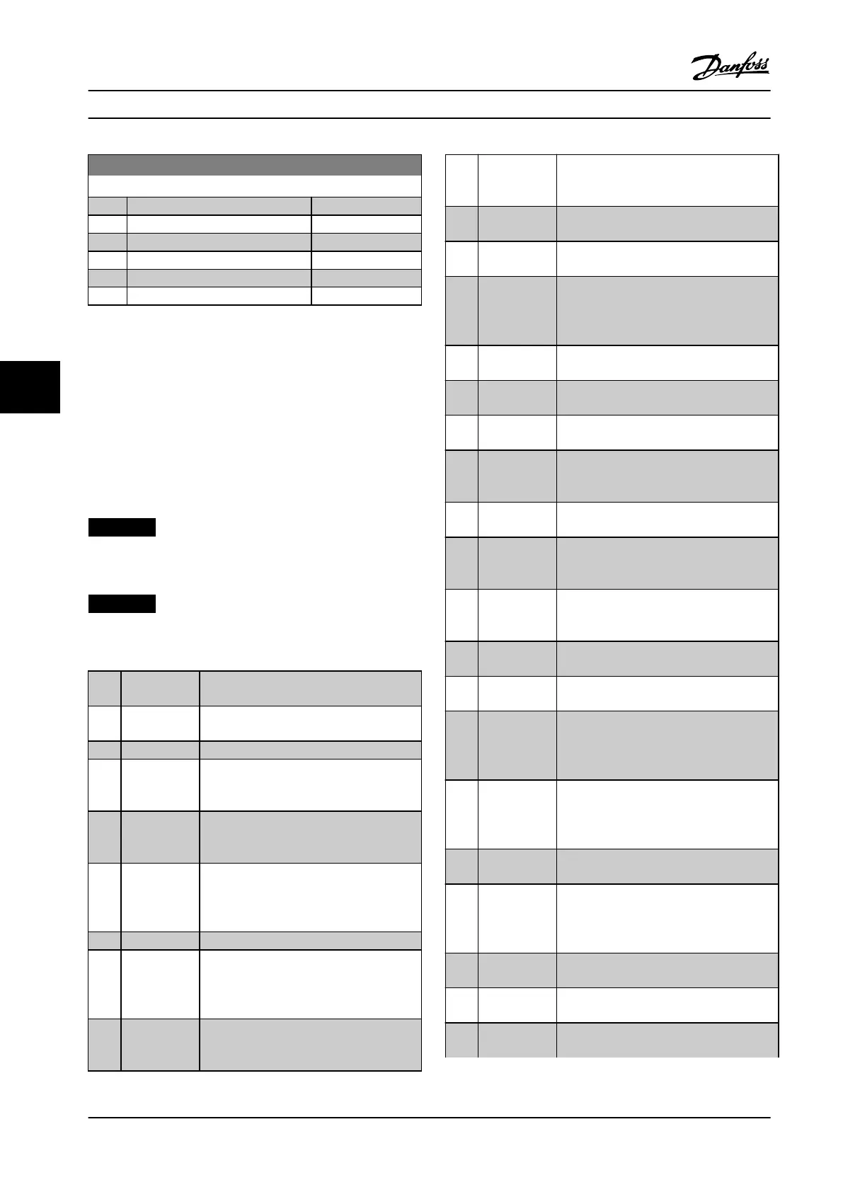
5-19 Terminal 37 Safe Stop
Option: Function:
[4] PTC 1 Alarm
[5] PTC 1 Warning
[6] PTC 1 & Relay A
[7] PTC 1 & Relay W
[8] PTC 1 & Relay A/W
[9] PTC 1 & Relay W/A
6.6.4 5-3* Digital Outputs
Parameters for conguring the output functions for the
output terminals. The 2 solid-state digital outputs are
common for terminals 27 and 29. Set the I/O function for
terminal 27 in parameter 5-01 Terminal 27 Mode, and set
the I/O function for terminal 29 in parameter 5-02 Terminal
29 Mode. Digital outputs appear if parameter 5-01 Terminal
27 Mode or parameter 5-02 Terminal 29 Mode are set to
output.
NOTICE!
These parameters cannot be adjusted while the motor is
running.
NOTICE!
Only for activating 24 V DC devices − restricted use for
relays.
The digital outputs can be programmed
with these functions:
[0] No operation Default for all digital outputs and relay
outputs
[1] Control ready The control board receives supply voltage.
[2] Drive ready The frequency converter is ready for
operation and applies a supply signal on
the control board.
[3] Drive ready /
remote
control
The frequency converter is ready for
operation and is in Auto On mode.
[4] Stand-by / no
warning
The frequency converter is ready for
operation. No start or stop command is
been given (start/disable). There are no
warnings.
[5] Running The motor is running.
[6] Running / no
warning
The output speed is higher than the speed
set in parameter 1-81 Min Speed for
Function at Stop [RPM]. The motor is
running and there are no warnings.
[7] Run on
reference / no
warning
The motor runs at reference speed.
[8] Run in
range / no
warning
The motor runs in speed range.
[9] Alarm An alarm activates the output. There are
no warnings.
[10] Alarm or
warning
An alarm or a warning activates the
output.
[11] At torque
limit
The torque limit set in
parameter 4-16 Torque Limit Motor Mode or
parameter 1-17 Voltage lter time const. has
been exceeded.
[12] Out of current
range
The motor current is outside the range set
in parameter 4-18 Current Limit.
[13] Below
current, low
The motor current is lower than set in
parameter 4-50 Warning Current Low.
[14] Above
current, high
The motor current is higher than set in
parameter 4-51 Warning Current High.
[15] Out of speed
range
The output speed is outside the range set
in parameter 4-52 Warning Speed Low and
parameter 4-53 Warning Speed High.
[16] Below speed,
low
The output speed is lower than the setting
in parameter 4-52 Warning Speed Low.
[17] Above speed,
high
The output speed is higher than the
setting in parameter 4-53 Warning Speed
High.
[18] Out of
feedback
range
The feedback is outside the range set in
parameter 4-56 Warning Feedback Low and
parameter 4-57 Warning Feedback High.
[19] Below
feedback low
The feedback is below the limit set in
parameter 4-56 Warning Feedback Low.
[20] Above
feedback high
The feedback is above the limit set in
parameter 4-57 Warning Feedback High .
[21] Thermal
warning
The thermal warning turns on when the
temperature exceeds the limit in the motor,
the frequency converter, the brake resistor,
or the thermistor.
[25] Reverse Reversing. Logic ‘1’ = relay activated, 24 V
DC when CW rotation of the motor. Logic
‘0’ = relay not activated, no signal, when
CCW rotation of the motor.
[26] Bus OK Active communication (no time-out) via
the serial communication port.
[27] Torque limit
and stop
Use in performing a coasting stop and in
torque limit condition. If the frequency
converter has received a stop signal and is
at the torque limit, the signal is Logic ‘0’.
[28] Brake, no
warning
The brake is active and there are no
warnings.
[29] Brake ready,
no fault
The brake is ready for operation and there
are no faults.
[30] Brake fault
(IGBT)
The output is Logic ‘1’ when the brake
IGBT is short-circuited. Use this function to
Parameter Descriptions
VLT
®
Compressor Drives CDS 302/CDS 303
66 Danfoss A/S © Rev. 2013-07-03 All rights reserved. MG34M422
6
6
 Loading...


