28-12 Fixed Boost Interval
Range: Function:
are performed even when no boosts have
occurred due to low ow speed
(parameter 28-11 Low Speed Running Time).
28-13 Boost Duration
Range: Function:
30 s * [10 – 120 s ] This parameter controls the duration of oil
return boosts.
6.15.3 28-2* Discharge Temperature
Monitor
The Discharge Temperature Monitor (DTM) can be used to
prevent the discharge temperature from reaching
dangerous levels.
Two temperature levels of increasing severity can be
programmed. These levels are referred to as "warning
level" (set in par. 28-24 Warning level) and "emergency
level," (set in par. 28-26 Emergency level) respectively, with
increasing severity. Each level corresponds to a particular
set of preventive actions.
Figure 6.37
Discharge temperatures above the emergency level cause
an alarm and an immediate trip to prevent damage to the
compressor.
Normal operations apply for discharge temperatures below
warning level. The discharge temperature is passively
monitored without aecting drive operations.
Discharge temperatures in the range from warning level to
emergency level trigger a warning and an action set by
parameter par. 28-25 Warning Action. The action can be
None or Decrease cooling. If the action is set to Decrease
cooling, cooling is decreased as a preventive action in an
attempt to lower the discharge temperature.
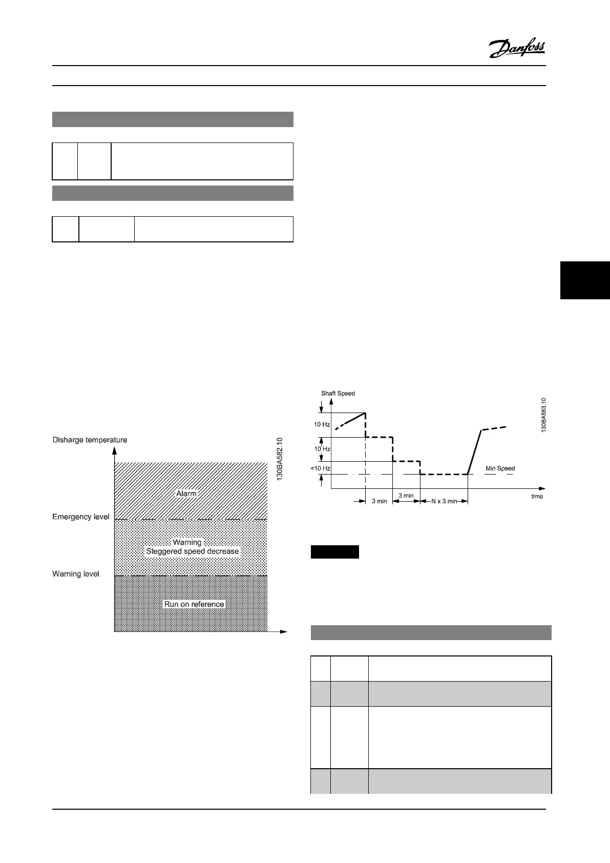
Cooling is decreased by step-wise lowering of the shaft
speed until the discharge temperature either drops below
warning level or exceeds emergency level. Each step
represents a three-minute period during which the
maximum allowed shaft speed is 10 Hz lower than the
previous step. The initial step occurs when the discharge
temperature exceeds the warning level and uses the
current shaft speed as the basis for the 10 Hz speed
reduction.
The speed steps enforce maximum shaft speeds. If the
reference corresponds to a lower speed, the reference is
obeyed. If it corresponds to a higher speed, the speed is
limited to the maximum shaft speed for that step.
Figure 6.38
NOTICE!
If the cascade controller is active, unwanted staging or
de-staging may result if the discharge temperature
monitor reduces the speed to Motor Speed Low Limit, par.
4-11 or 4-12.
28-20 Temperature Source
Option: Function:
Selects the input terminal to which the discharge
temperature measurement device is connected.
[0]
*
None No Source. The Discharge Temperature Monitor is
not active.
[1] Analog
input 53
The measurement device is connected to input
terminal 53. Program parameter 6-10 Terminal 53
Low Voltage to parameter 6-15 Terminal 53 High
Ref./Feedb. Value to match the characteristics of
the device.
[2] Analog
input 54
The measurement device is connected to input
terminal 54. Program parameter 6-20 Terminal 54
Parameter Descriptions Operating Instructions
MG34M422 Danfoss A/S © Rev. 2013-07-03 All rights reserved. 123
6
6
 Loading...


