6.5 Parameters: 4-** Limits/Warnings
6.5.1 4-1* Motor Limits
Dene torque, current and speed limits for the motor, and
the reaction of the frequency converter when the limits are
exceeded.
A limit may generate a message on the display. A warning
will always generate a message on the display or on the
eldbus. A monitoring function may initiate a warning or a
trip, upon which the frequency converter will stop and
generate an alarm message.
4-20 Torque Limit Factor Source
Option: Function:
Select an analog input for scaling the
settings in parameter 4-16 Torque Limit
Motor Mode and parameter 4-17 Torque
Limit Generator Mode from 0% to 100%
(or inverse). The signal levels
corresponding to 0% and 100% are
dened in the analog input scaling, e.g.
parameter group 6-1* Analog Input 1.
This parameter is only active when
parameter 1-00 Conguration Mode is in
Speed Open Loop or Speed Closed Loop.
[0] No function
[2] Analog in 53
[4] Analog in 53 inv
[6] Analog in 54
[8] Analog in 54 inv
[10] Analog in X30-11
[12] Analog in X30-11
inv
[14] Analog in X30-12
[16] Analog in X30-12
inv
4-21 Speed Limit Factor SourceOption
Option: Function:
Select an analog input for scaling the
settings in parameter 4-19 Max Output
Frequency from 0% to 100% (or vice
versa). The signal levels corresponding
to 0% and 100% are dened in the
analog input scaling, e.g. parameter
group 6-1* Analog Input 1. This
parameter is only active when
parameter 1-00 Conguration Mode is in
Torque Mode.
[0] * No function
[2] Analog input 53
[4] Analog input 53
inv
4-21 Speed Limit Factor SourceOption
Option: Function:
[6] Analog input 54
[8] Analog input 54
inv
[10] Analog input
X30-11
[12] Analog input
X30-11 inv
[14] Analog input
X30-12
[16] Analog input
X30-12 inv
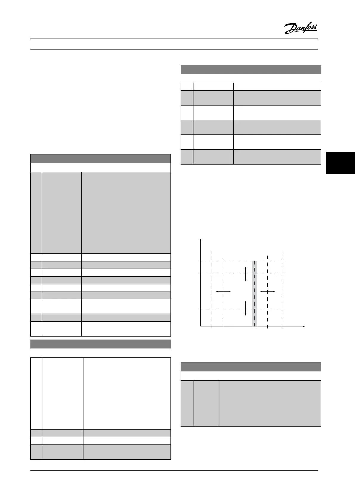
6.5.2 4-5* Adjustable Warnings
Use these parameters to adjust warning limits for current,
speed, reference and feedback.
Warnings are shown on the LCP, and can be programmed
to be outputs or to be read out via serial bus in the
Extended Status Word.
130BA064.10
(P 4-18)
(P 4-51)
(P 4-50)
(P 4-11) (P 4-53)(P 4-52) (P 4-13)
I
HIGH
I
LOW
n
LOW
n
HIGH
n
motor
I
motor
REF
ON REF
IN RANGE
I
LIM
n
MAX
n
MIN
[RPM]
Figure 6.6 Adjustable Warnings
4-50 Warning Current Low
Range: Function:
0 A* [ 0 - par.
4-51 A]
Enter the I
LOW
value. When the motor current
falls below this limit, the display reads Current
Low. The signal outputs can be programmed to
produce a status signal on terminal 27 or 29
and on relay output 01 or 02. Refer to
Figure 6.6.
Parameter Descriptions Operating Instructions
MG34M422 Danfoss A/S © Rev. 2013-07-03 All rights reserved. 59
6
6
 Loading...


