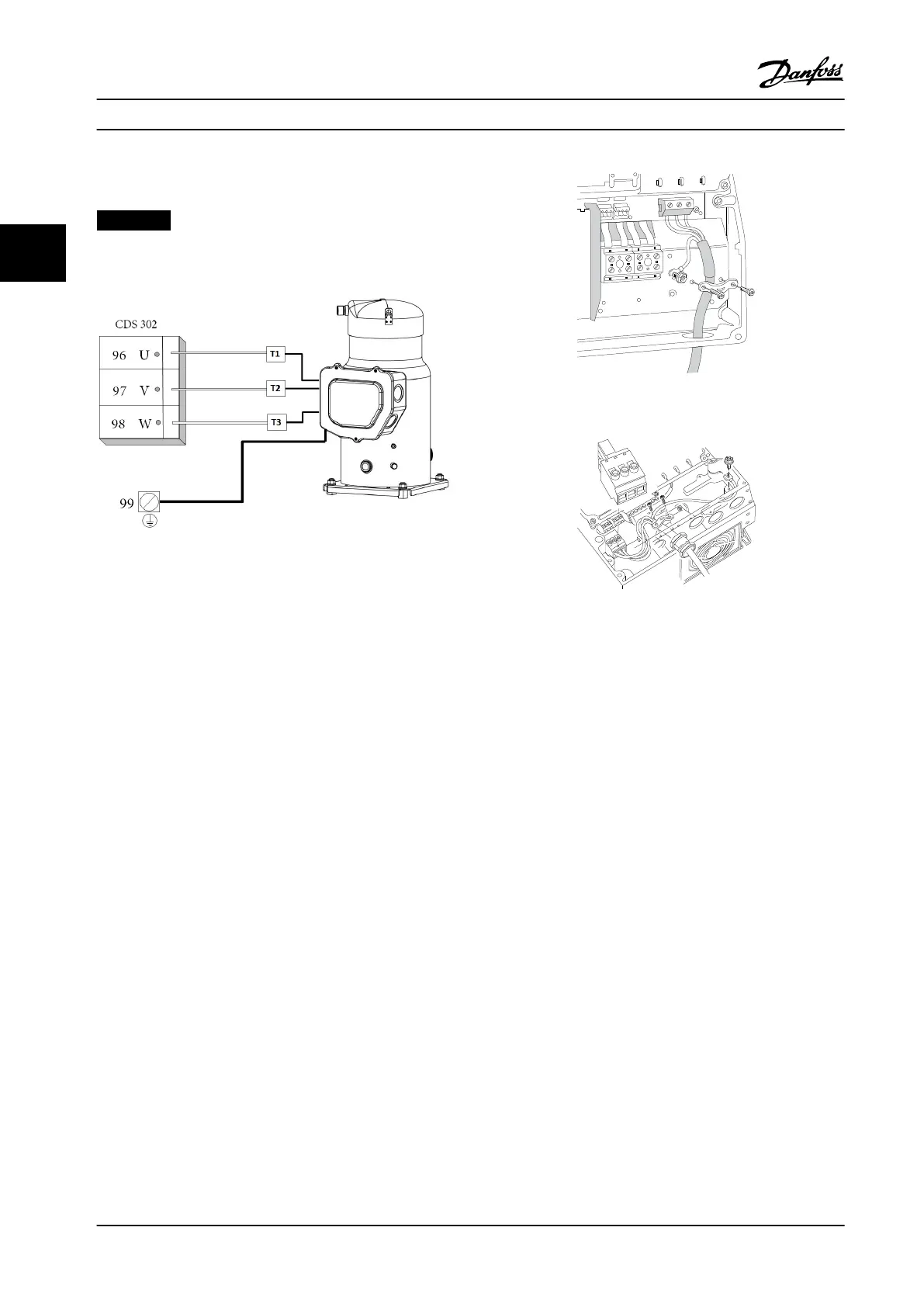
3.3.5 Motor Compressor Connection
NOTICE!
Always wire terminal 96 (U) to T1, 97 (V) to T2, and 98
(W) to T3.
Figure 3.13 Motor/Compressor Wiring
Motor compressor cable must be screened/armored. If an
unscreened/unarmored cable is used, some EMC
requirements are out of compliance. For more information,
see EMC specications.
1. Fasten decoupling plate to the bottom of the
frequency converter with screws and washers
from the accessory bag.
2. Attach motor compressor cable to terminals 96
(U), 97 (V), 98 (W).
3. Connect to ground connection (terminal 99) on
decoupling plate with screws from the accessory
bag.
4. Insert terminals 96 (U), 97 (V), 98 (W) and motor
compressor cable to terminals labeled MOTOR.
5. Fasten screened cable to decoupling plate with
screws and washers from the accessory bag.
6. Connect U, V, W for motor compressor clockwise.
Figure 3.14 How to Connect to Motor Terminals B1/B2
L 1
L 2
L 3
91
92
93
130BT336.10
Figure 3.15 How to Connect to Mains and Ground without
Mains Disconnect
3.3.6 Motor Compressors Cables
Correct dimensioning of motor compressor cable cross-
section and length is described in the application manual.
•
Use a screened/armored motor compressor cable
to comply with EMC emission specications
•
Keep the motor compressor cable as short as
possible to reduce the noise level and leakage
currents
•
Connect the motor compressor cable screen to
both the decoupling plate of the frequency
converters and to the metal cabinet of the motor
compressor
•
Make the screen connections with the largest
possible surface area (cable clamp). Use the
supplied installation devices in the frequency
converter for making the screen connections.
How to Install
VLT
®
Compressor Drives CDS 302/CDS 303
20 Danfoss A/S © Rev. 2013-07-03 All rights reserved. MG34M422
33
 Loading...


