Chapter 4 Installing Hardware
4-35
4.8 Wiring Analog Input / Output Modules
Definitions of the terminals
◆ Two/three-wire (passive sensor): the sensor and the system share the same power circuit.
◆ Four-wire (active sensor): the sensor uses an independent power supply and should not share the same
power circuit with the system.
◆ Note: use cables with the same length (less than 200 m) and use terminal resistors of less than 100
ohm.
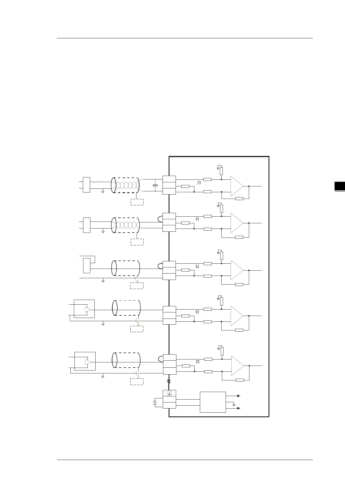
4.8.1 Wiring DVP04AD-E2
Shi elded cable *1
-10V~+10V
V I+
I1+
VI1-
CHX
V 3+
I3+
V I3 -
*3
* 2
CH1
1M
CH3
AG
1M
1M
A G
1M
250
25 0
0V
24 V
24 VDC
DC/DC
Converter
+15V
-15V
A G
FE
*4
*5
+
-
-20mA ~+20mA
V 2+
I2+
V I2 -
* 2
CH2
1M
A G
1M
25 0
*4
FE
+
-
+
-
+24V
0V
V4+
I4+
V I4 -
CH4
1M
A G
1M
25 0
+2 4V
0V
4mA ~+20mA
CH1
1M
A G
1M
25 0
-20mA~+20m A
+24V
+
-
V 1+
I1+
V I1 -
*2
-10V~+10V
+2 4V
+
-
* 4
FE
*4
FE
*4
FE
0V
+2 4V
0V
0V
*6
CHX
*6
CHX
* 6
CHX
*6
CHX
* 6
Shi elded cable *1
Shi elded cable *1
Shi elded cable *1
Shi elded cable *1
4-wir e: voltage inp ut
4-wir e: c urr ent inp ut
2-wire: current input
3-wire: voltage inpu t
2-wire: current input
3-wire: current inpu t
*1. Use shielded cables to isolate the analog input signal cable from other power cables.
*2. If the module is connected to a current signal, the terminals Vn and In+ (n=1–4) must be short-circuited.
 Loading...


