DVP-ES3 Series Operation Manual
5-2
5.1 Introduction to CPU Devices
This section describes the values and strings processed by the PLC. It also describes the functions of devices, including
input, output and auxiliary relays, as well as timers, counters, and data registers. The PLC simulates external devices in
the PLC’s internal memory, so the word “device” is a generic name that refers to all the internal memory locations in the
PLC. A device can be a bit device or a word device. Bit devices simulate coils, contacts and flags, while word devices
simulate registers.
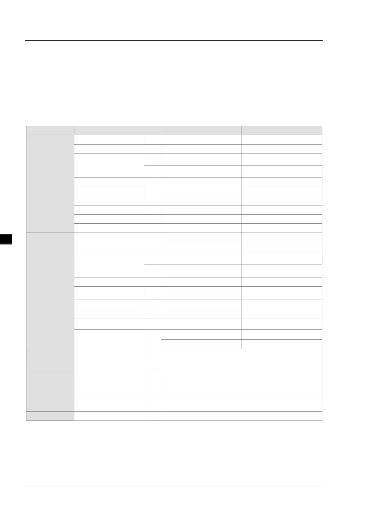
5.1.1 Device Table
Bit device
Data register
D 48,0000 D0.0–D29999.15
W 48,0000
W0.0–W29999.15 *
4
32-bit counter HC 256 HC0–HC255
Word device
Data register
D 30000 D0–D29999
W 30000
W0–W29999 *
4
File register FR 65536 FR0–FR65535
32-bit counter HC
256(512 words)
HC0–HC255
Index register E
10 E0–E9
5
E10–E14 *
4
Constant*
1
Decimal system K
16 bits: -32768 to 32767
32 bits: -2147483648 to 2147483647
Constant*
2
Hexadecimal system 16#
16 bits: 16#0–16#FFFF
32 bits: 16#0–16#FFFFFFFF
Single-precision
F 32 bits: ±1.17549435
-38
to ±3.40282347
+ 38
3
*1: Constants are indicated by K in the device lists in Chapter 5 and Chapter 6 in the DVP-ES3 Series Programming
Manual. For example, when “K50” appears in the DVP-ES3 Series Programming Manual, enter only the number 50 in
ISPSoft.
*2: Floating-point numbers are indicated by F/DF in the device lists in Chapter 5 and Chapter 6 in the DVP-ES3 Series
Programming Manual, but they are represented by decimal points in ISPSoft. For example, for the floating-point
 Loading...


