Chapter 5 CPU and Module Devices
5-5
5.2. CPU Device Functions
The following flow chart shows the procedure for processing a program in the PLC.
Input terminal X
Device memory
Processing the program
Device memory
Regenerating the output signal
and sending it to the output terminal
Regenerating the input signal
Device memory
Regenerating the input signal
1. Before the program is executed, the state of the
external input signal is read into the memory location
for the input signal.
2. When program is executed, the state in the memory
location for the input signal does not change even if
the input signal changes from ON to OFF or from OFF
to ON. The input signal is not refreshed until the next
scan begins.
Processing the program
After the input signal is refreshed, the instructions in the
program are executed in order from the start address of the
program. The results are stored in the device memory.
Regenerating the state of the output
After the instruction END is executed, the state in the
device memory is sent to the specified output terminal.
5.2.1 Values and Constants
A bit is the basic unit in the binary system. Its state is either 1 or 0.
Nibble
A nibble is composed of four consecutive bits (for example b3–b0). Nibbles
can represent 0–9 in the decimal system, or 0–F in the hexadecimal system.
Byte
A byte is composed of two consecutive nibbles ( 8 bits, b7–b0). Bytes can
represent 00–FF in the hexadecimal system.
Word
A word is composed of two consecutive bytes (16 bits, b15–b0). Words can
represent 0000–FFFF in the hexadecimal system.
Double word
A double word is composed of two consecutive words (i.e. 32 bits, b31–b0).
Double words represent 00000000–FFFFFFFF in the hexadecimal system.
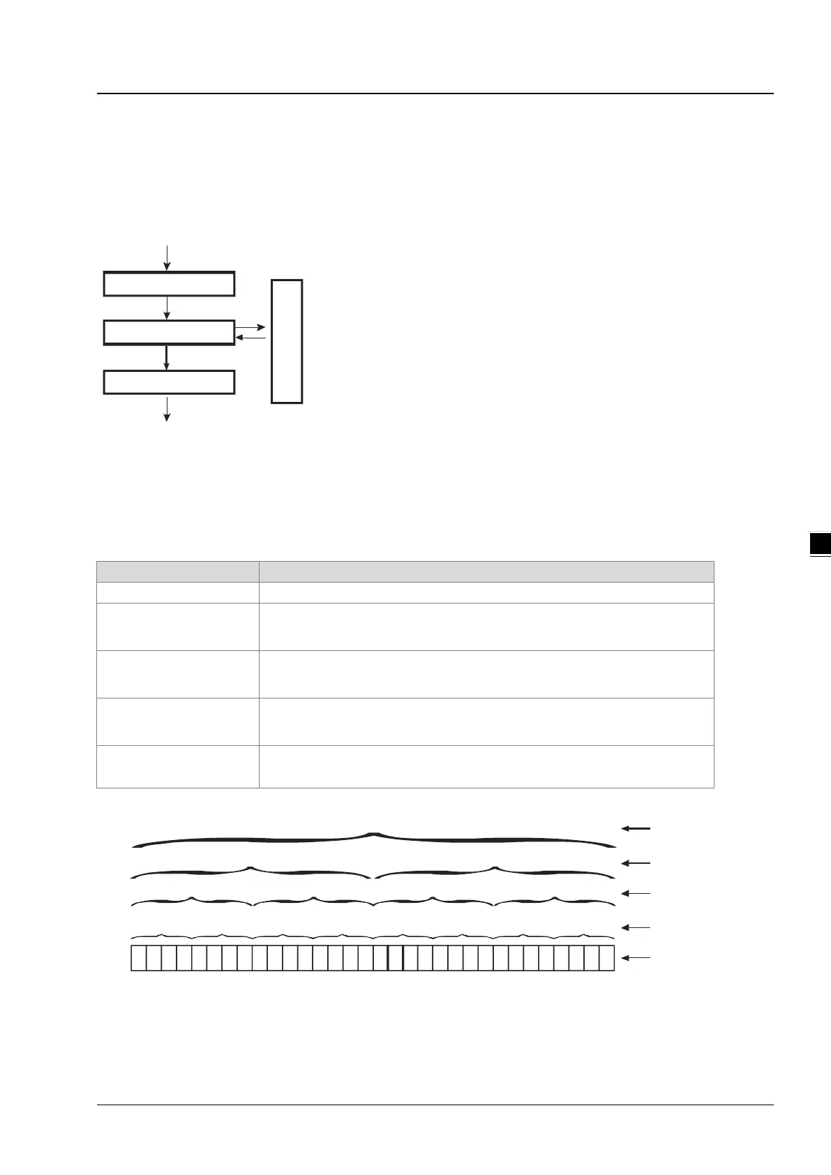
The relation among bits, nibbles, bytes, words, and double words in the binary system is shown in the picture below.
b31b30 b29 b28 b27b26 b25 b24
b23
b
22 b21 b20b19 b18 b17 b16 b15b14
b13
b12b 11 b10
b9 b8
b7
b6
b5 b4
b3
b2 b1 b0
NB0NB1NB2NB3NB4NB5NB6NB7
BY3 BY2 BY1 BY0
W1
DW
W0
Double word
Word
Byte
Nibble
Bit