Chapter 2 Specifications and System Configuration
2-24
S-type:K0 ~ K17,500
T-type:K-1,500 ~ K3,900
E-type:K-1,500 ~ K9,800
N-type:K-1,500 ~ K12,800
S-type:K320 ~ K31,820
T-type:K-2,380 ~ K7,340
E-type:K-2,380 ~ K17,960
N-type:K-2,380 ~ K23,360
Hardware resolution
16-bit (0.1°C) 16-bit (0.1°F)
16-bit
Average function
Yes, CR#8 ~ CR#11, setting range: K1 ~ K100
Self-diagnosis
Detecting if exceeding upper and lower limts or channel disconnection
Isolation
An analog circuit is isolated from a digital circuit by a d
igital integrated circuit/an
optocoupler, and the analog channels are isolated from one another by
optocouplers.
Isolation between a digital circuit and a ground: 500 VDC
Isolation between an analog circuit and a ground: 500 VDC
Isolation between an analog circuit and a digital circuit: 500 VDC
Isolation between the 24 VDC and a ground: 500 VDC
Isolation between analog channels: 120 VAC
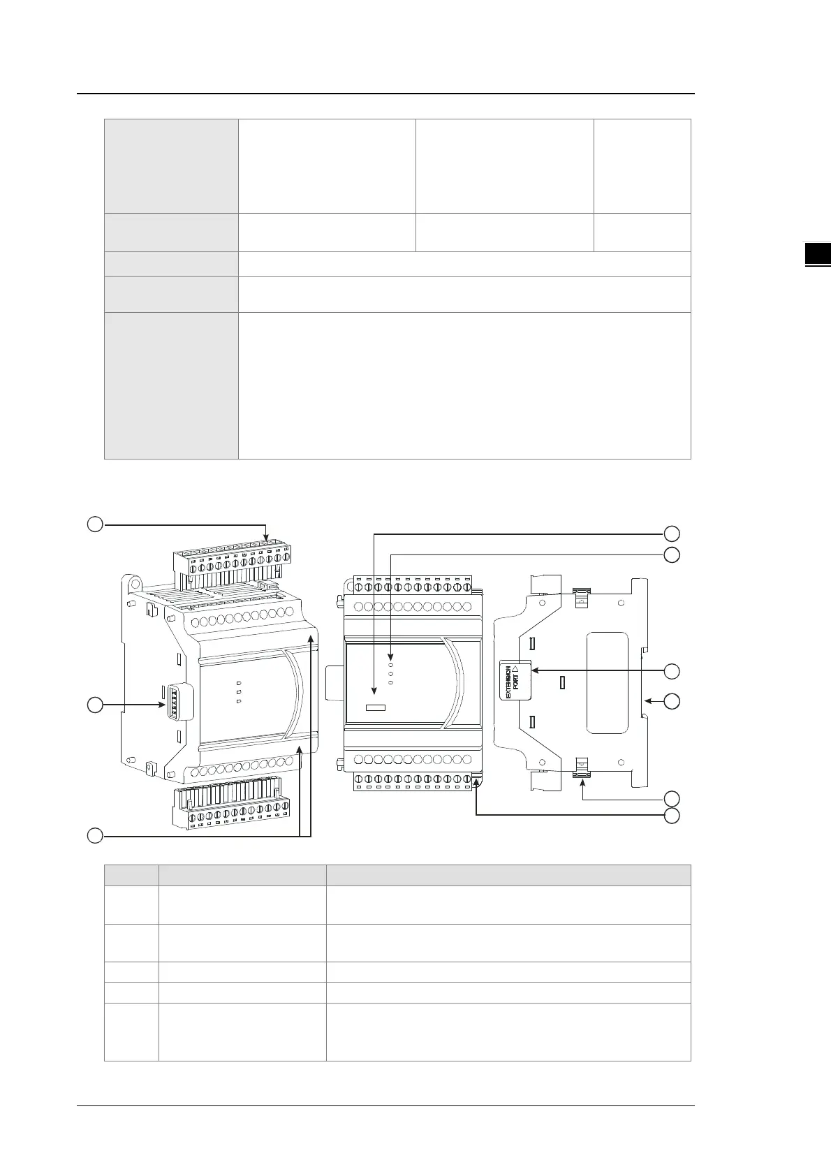
2.5.2 Temperature Measurement Module Profiles
1
4
5
3
6
7
8
2
9
0 4PT- E2
4AI-P T
Unit: mm
1 Removable terminal block
The inputs are connected to sensors.
The outputs are connected to loads to be driven.
2
External module connection
port
Connects the modules
5 POWER LED indicator
Indicates the status of the power supply
ON: the power is on
 Loading...


