DVP-ES3 Series Operation Manual
5-4
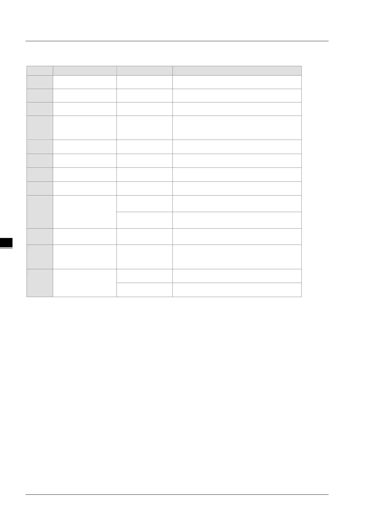
5.1.4 Latched Areas in the Device Range
X
Input relay X0–X377
All devices are non-latched.
Y
Output relay Y0–Y377
All devices are non-latched.
M*
1
Auxiliary relay M0–M8191 The default range is M6000–M8191.
SM
Special auxiliary relay SM0–SM2047
Some devices are latched, and cannot be
changed. Refer
to the list of special auxiliary
relays for more information.
S*
1
Flag S0–S2047 The default range is S512–S1023
T
Timer T0–T511 All devices are non-latched.
C*
1
Counter C0–C511 The default range is C448–C511
HC*
1
32-bit counter HC0–HC255 The default range is HC128–HC255
D*
1
Data register
D0–D29999 The default range is D20000–D29999
W0–W29999
*
2
FR
File register FR0–FR65535 All devices are latched.
SR
Special data register SR0–SR2047
Some are latched, and cannot be changed. Refer
to the list of special data registers for more
E
Index register
E0–E9 All devices are non-latched.
E10–E14
*
2
*1: For more information on setting the latched area, see HWCONFIG in ISPSoft. Setting the latched area means the
other areas are seen as non-latched areas. The range of latched areas cannot exceed the device range. For example,
setting M600–M7000 as latched areas makes M0–M5999 and M7001–M8191 non-latched areas.
*2: Used for editing in ISPSoft only.
 Loading...


