Chapter 2 Specifications and System Configuration
2-16
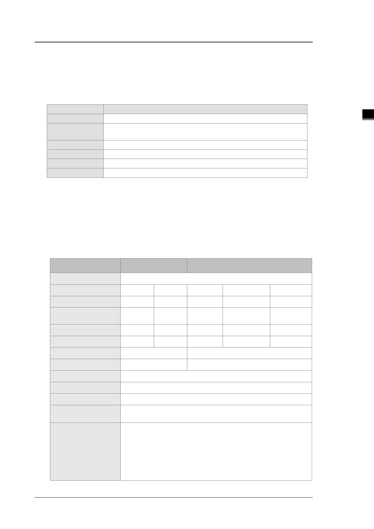
2.4 Analog Input/Output Module Specifications
2.4.1 General Specifications
DVP04AD-E2
Electrical specifications
Four
Analog-to-digital
Voltage input/Current input
24 VDC (20.4 VDC–28.8 VDC) (-15% to +20%)
Removable terminal block (distance to the terminal is 5 mm)
Things to note when connecting the module to a CPU PLC module:
1. Up to 8 modules can be connected to a CPU PLC module.
2. The connected module is numbered automatically from 0 (nearest to the CPU PLC module) to 7
(furthest away from the CPU PLC module).
3. The connected modules do NOT take up any digital I/O points.
Functional specifications
Analog/digital module Voltage input Current input
Analog input channel
4 channels
Rated input range
±10V ±5V ±20 mA 0 ~ 20 mA 4 ~ 20 mA
Digital conversion range
±32,000 ±32,000 ±32,000 0 ~ 32,000 0 ~ 32,000
Hardware input limit*
1
±10.12V ±5.06V ±20.24 mA -0.24~20.24 mA
3.81~20.19
Digital conversion limit*
2
±32,384 ±32,384 ±32,384 -384 ~+32,384 -384 ~+32,384
Hardware resolution
14-bit 14-bit 14-bit 13-bit 13-bit
Input impedance
≧1M Ω
250 Ω
Absolute input range*
3
±15 V ±32 mA
Digital data format
16-bit two’s complement number
Average function
Yes, CR#8 ~ CR#11, setting range: K1 ~ K100
Self-diagnosis function
Detecting if exceeding upper and lower limts or channel disconnection
Overall Accuracy
25° C/77° F: The allowed error range is ±0.5% of full scale.
0° C to 55° C/-32° F to 131° F: The allowed error range is ±1% of full scale.
Isolation
An analog circuit is isolated from a digital circuit by a digital integrated
circuit/an optocoupler, but the analog channels are not isolated from one
another.
Isolation between a digital circuit and a ground: 500 VDC
Isolation between an analog circuit and a ground: 500 VDC
Isolation between an analog circuit and a digital circuit: 500 VDC
Isolation between the 24 VDC and a ground: 500 VDC
 Loading...


